|
|
|
– › Wiring
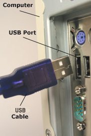
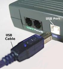
Diagrams » Cables » USB USB - Universal Serial Bus 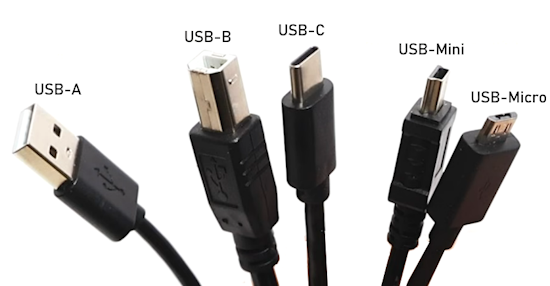 Universal Serial Bus (USB) is an electronics industry standard that specifies the physical interfaces and protocols for connecting, data transferring and powering of personal computers, peripherals, keyboards and mobile devices. USB was designed to standardize the connection of peripherals to computers, replacing various interfaces such as serial ports and parallel ports. It has become commonplace on a wide range of devices, such as keyboards, mice, cameras, printers, scanners, flash drives, smartphones, game consoles, and power banks. USB consists of four generations of specifications: USB 1.‘‘x’’, USB 2.0, USB 3.‘‘x’’, and USB 4. Color designations and data transfer speeds for the different USB generations are as follows: White - USB 1.0 - 1996 - 12 Mbps White - USB 1.1 - 1998 - 12 Mbps Black - USB 2.0 - 2000 - 480 Mbps Blue - USB 3.0 - 2008 - 5 Gbps Teal - USB 3.1 - 2013 - 5 Gbps and 10 Gbps Yellow - USB 3.1 - Power Delivery None - USB 3.2 - 2017 - 20 Gbps With the USB 4 standard (2019 - 40 Gbps) which uses the USB-C connector, the color codes are not used. 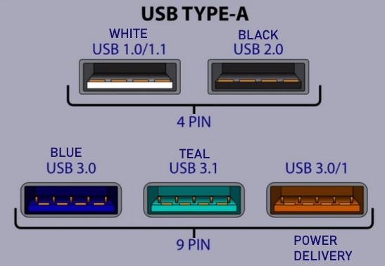 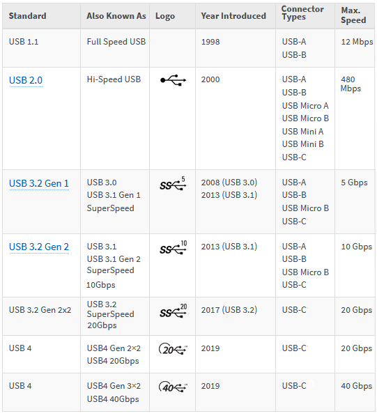 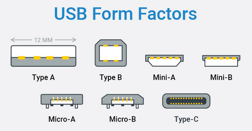 Identifying the correct USB-C Cable USB-C cables contain between 5 and 16+ active wires depending on capability, fundamentally including VBUS (power), GND (ground), and CC (configuration channel) lines. 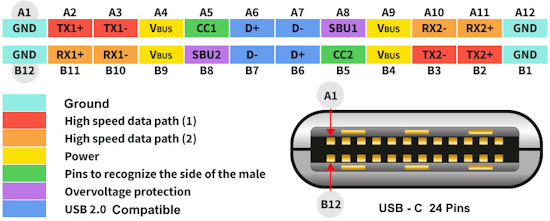 While connectors have 24 pins, they are rarely all wired, usually just USB 2.0 data, high-speed lanes, and power delivery. This can create confusion with different USB-C cables because the cables are not all the same. Some USB-C cables only have wires to charge (power) and are usually thinner while others have additional wires to charge, transfer data and handle video and audio. 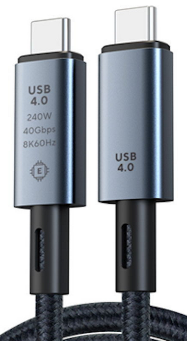 If you want a USB-C cable with full capability, be sure to get a cable marked with USB 4, 240W, 40Gbps and 8K60Hz. Key Internal Wire Structure USB-C cable (240W 40Gbps): Power & Ground (High Current): Multiple thick, tin-plated copper wires (often 2-4 for VBUS, 4+ for Ground/Bare) to handle 5A current and reduce resistance. Data Pairs (40Gbps): Four shielded differential pairs used for USB4/Thunderbolt speeds. USB 2.0 Data: Dedicated D+/D- wires (Green/White) for legacy compatibility. Configuration & Management: CC (Configuration Channel) and VCONN wires for power negotiation and E-marker communication. Shielding: Inner Aluminum foil shielding and outer braided shielding to handle high frequencies (40Gbps) and reduce EMI. E-Marker Chip: Inside the connector, identifying the cable as capable of 240W/40Gbps. "Charging Only" Cables: Cables that come with phones or low-cost chargers are often USB 2.0 and do not support video output. Key Pins for USB-C Video (Alt Mode) High-Speed Data Paths (TX/RX): The 8 pins (A2-A3, A10-A11, B2-B3, B10-B11) allow for 4 lanes of high-speed signaling for high-resolution video. SBU1/SBU2 (A8/B8): Sideband Use pins are used to carry audio and setup signals (AUX channel) for DisplayPort/HDMI mapping. CC1/CC2 (A5/B5): Configuration Channel pins detect the connection, orientation, and determine if the cable should enter "Alt Mode" for video. Not All Cables Support Video: Only full-featured USB-C cables (USB 3.1 or higher, e.g., USB4/Thunderbolt) contain the necessary wires for video. High-speed data in a USB-C cable (USB 3.x/4) uses four differential pairs— TX1+/TX1-, TX2+/TX2-, RX1+/RX1-, and RX2+/RX2-—designed for high-speed differential signal transmission. These 8 pins enable dual-lane operation for maximum throughput, while standard USB 2.0 uses dedicated pins. High-Speed Data Pins (USB 3.0/4.0): RX1±/TX1± and RX2±/TX2± (8 pins total) for SuperSpeed/Ultra-High speed data transfer. USB 2.0 Data Pins: (Pins A6/A7 or B6/B7) for legacy compatibility. Configuration & Management: The CC (Channel Configuration) pins handle speed negotiation and orientation. Do usb-c cables use the same 8 pins for video and high speed data? Yes, fully featured USB-C cables use the same high-speed differential pairs—specifically four pairs totaling 8 pins—to carry both high-speed data (USB 3.x/4) and video signals (DisplayPort Alt Mode). These are usually for high-speed transmission. However, many USB-C cables are designed only for charging or USB 2.0, lacking these necessary internal pins. High-Speed Lanes (8 Pins): Used for 10/20/40/80 Gbps data and video via DisplayPort Alt Mode. USB 2.0 Pair: Cheaper, thinner cables often only have wires for USB 2.0 (480 Mbps) and cannot transmit video. What is DisplayPort Alt Mode? DisplayPort Alt Mode (DP Alt Mode) is a USB-C feature that allows a computer, phone, or tablet to directly output video signals through its USB-C port to a monitor. It transforms the USB-C connector into a native DisplayPort interface, supporting 4K, 8K, and high-resolution video using only one cable. Do USB-C cables use specific pins for audio? Yes, particularly in "Audio Adapter Accessory Mode". Analog audio maps to the SBU1/SBU2 (Sideband Use) pins for microphone and ground, and the D+/D- (USB 2.0 Differential Pair) pins for left/right stereo audio channels. SBU1 and SBU2 (Sideband Use) pins in a USB-C connector are primarily used for low-speed signaling to enable Alternate Modes (such as DisplayPort or Thunderbolt) and Audio Accessory Mode. They are not used for standard USB data transfer, but rather to manage external protocols, such as carrying DisplayPort AUX channel signals for video. Key Uses of SBU1 and SBU2: DisplayPort Alternate Mode: Used as the AUX channel (differential pair) to manage display settings, such as resolution and refresh rate, between the source and display. Thunderbolt 3/4: Utilized for sideband signaling to establish and manage the high-speed data link. Audio Accessory Mode: Allows USB-C ports to act as an analog audio jack (for headphones/headsets), with SBU pins carrying the audio signals. SBU1/SBU2 over voltage protection is a safety feature, while audio is a functional mode that repurposes those pins. USB-C designs must provide Over Voltage Protection on SBU lines even when they are being used for audio, as a short to VBUS can happen at any time. What is MHL? Many older Android smartphones and tablets, primarily from 2012–2015, support MHL (Mobile High-Definition Link) via Micro-USB to output HDMI video. Key supported devices include the Samsung Galaxy S2–S5, Galaxy Note 1–4, Sony Xperia Z series, and many HTC One devices. Using a 5-pin or 11-pin MHL adapter, these phones mirror their display directly to TVs, usually requiring external USB power to function. Supported Micro-USB MHL Devices MHL was most common on high-end devices from the micro-USB era. Note that Samsung devices from the S3/Note 2 onward often require a 5-pin to 11-pin adapter. Samsung: Galaxy S5, S4 (including Active/Zoom), S3, S2, Galaxy Note 4, Note 3, Note II (N7100), Note, Galaxy Tab 3 (8.0, 10.1), Note 8.0, Galaxy Tab S. Sony: Xperia Z, Z1, Z2, Z3, ZL, V, Tablet Z. HTC: One (M8), One (M7), One X, One X+, One S, Sensation, Evo 3D, Butterfly. LG: Optimus G, G2, G Pro, GK. Huawei: Honor 6, Honor 7, Ascend P2, P1. Important MHL Requirements Hardware Support: MHL must be built into the phone's hardware; it cannot be added via software updates. 5-Pin vs 11-Pin: Most devices use 5-pin, but Samsung Galaxy S3/S4/Note series use a proprietary 11-pin connector, often needing a specific JUEJUEZI MHL Adapter. External Power: MHL adapters require the USB port on the adapter to be plugged into a power source (TV USB or wall charger). Most modern Android phones have dropped MHL support in favor of wireless casting or proprietary desktop modes (like Samsung DeX) Syntech USB C to USB Adapter Pack of 2 USB C Male to USB 3.0 Female Adapter Compatible with MacBook Pro Air 2024, iPad Pro, Samsung Notebook, Dell XPS, iPhone 15 and More Type C Devices. • USB-C adapter for USB 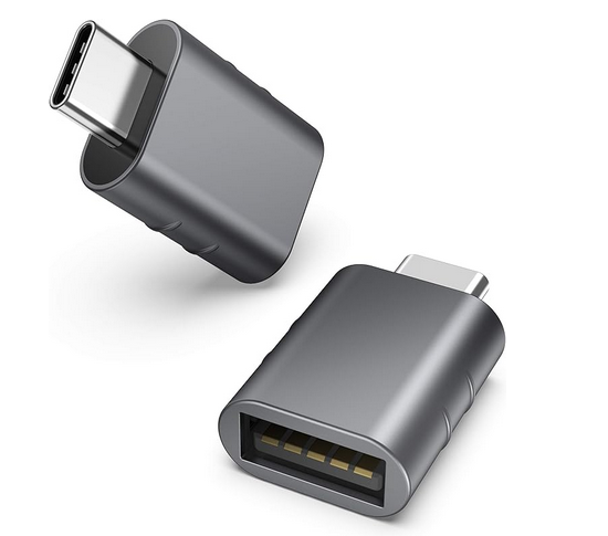 USB-C To Ethernet Adapter  • USB-C adapter for RJ-45 Ethernet Laptop has only USB-C port but you need RJ-45 Ethernet, use adapter. 𝐏𝐥𝐮𝐠 & 𝐏𝐥𝐚𝐲: This Ethernet cable adapter has driver-free installation for Windows 10, Mac OS (10.9 and later), Chrome OS, and Linux OS. 𝐂𝐨𝐦𝐩𝐚𝐭𝐢𝐛𝐥𝐞 𝐰𝐢𝐭𝐡 𝐌𝐨𝐬𝐭 𝐔𝐒𝐁-𝐂 𝐃𝐞𝐯𝐢𝐜𝐞𝐬: Supports Windows 11/10/8.1/8/7, Chrome OS, MacOS, Linux (Ubuntu) for PCs, Macs, tablets, and more. USB Type-C USB-C™  USB-C is a universal standard that enables charging, syncing data and playing audio and video. The Apple iPhone late models have a USB-C connector, which allows you to charge and connect to a variety of external storage devices and displays. You can use the USB-C connector to listen to sound with wired headphones. You can connect your iPhone to an HDMI TV with a USB-C to HDMI adapter or cable. Adapters and cables that support HDMI 2.0 can output video from iPhone at 4K video resolution and 60 Hz. To use Lightning accessories, you can use the USB-C to Lightning adapter, which supports power, data and audio. USB-C™, also known as USB Type-C™, is a connector developed by the USB Implementers’ Forum (USB-IF), a group of industry leaders within the consumer electronics community. USB-C™ will gradually replace previous USB types, including USB-A, USB-B and USB Mini-B. As future devices are equipped with the USB-C™ port, which is smaller than its predecessors, it’s likely that these devices will also be thinner, lighter, and more compact than ever before. WHY IS USB-C™ BETTER THAN EXISTING USB CABLES? USB-C™ is very user friendly and it has a reversible connector. There’s no up or down orientation so it works regardless of which way you plug it in. Truly universal. Not just happy to work with smartphones, tablets, laptops, digital cameras, or anything that traditionally connects via USB, USB-C™ is also at home across different operating systems like iOS, Android, Windows, Google and more. USB-C™ can transfer data at speeds up to 10Gbps (gigabits per second). That’s up to 20 times faster than USB 2.0. Not only is it fast, there’s so much more power. With up to 100 watts, or 3 amps of power, USB-C™ cables can power almost anything from laptops to large high-resolution monitors, even some printers. Also, USB-C™ cables can deliver Ultra-HD 4K video resolution to USB-C™ and HDMI displays. When transitioning to USB-C™, it doesn’t mean you have to replace all your existing devices. Your new USB-C™ device (such as a laptop) will still be compatible with all your existing devices (smartphones, tablets, mouse, printer, etc.), you just need the correct USB-C™ cable or adapter. 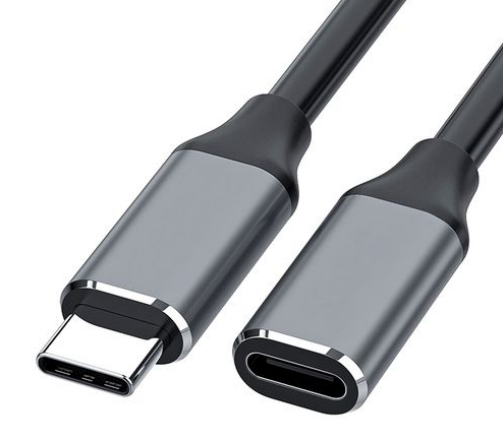 WHAT’S BEHIND THE MOVE TO USB-C™? USB Type-C is bi-directional, meaning that when plugged in, a device can receive and send data. USB-C is faster, meaning that large files such as movies, DSLR images, and high-end audio can be transferred in seconds. The USB-C™ connector is being widely adopted by manufacturers including Apple, Google and Microsoft. With such widespread support from these market-leading manufacturers, it’s only a matter of time before this standard becomes the norm. IS USB TYPE-C™ THE SAME AS USB 3.1? Although USB-C™ and USB 3.1 were developed at the same time, they are not the same thing. USB 3.1 is an upgrade from the familiar USB 2.0, and more recent USB 3.0, offering significantly faster data transfer. USB-C™ is not backward compatible. USB 3.1 is the technology. The USB-C™ is a connector that enables the functionality to support the technology. WHAT IS USB POWER DELIVERY? USB Power Delivery, or USB PD, is a charging protocol that uses high speed USB-C™ connecters and cables. Smartphones, tablets, and laptops that are Power Delivery-enabled allow safe, faster charging and more power for larger devices, without the need of a separate power supply. USB PD will charge your smartphone up to 70% faster than standard 5W charging. You can even share power between USB PD devices.  USB (Universal Serial Bus) is a data transfer interface between a computer (PC) and peripherals (like audio players, digital cameras and printers), which allows you to plug in a device without adding an adapter card in the computer. Universal Serial Bus (USB) is a connectivity specification developed by the USB Implementers Forum (IF). USB is aimed at peripherals connecting outside the computer in order to eliminate the problem of opening the computer case for installing cards needed for certain devices. USB provides for ease of use, expandability, and speed for the end user. USB is easier to use than some of the traditional internal PC buses, such as PCI and ISA. The devices that use USB are hot-pluggable, eliminating the need to shut down the PC to add or remove a device. A USB bus also has automatic device detection; once you plug in your device, the operating system software should detect, install, and configure the device automatically. USB symbol used on cables and ports indicating Universal Serial Bus. 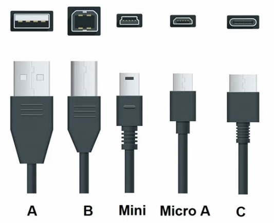 Type A is used on desktop computers, Type B on printers, Type C on Android phones. Adapter cables are used to connect one type to another. USB THUMB DRIVE (Flash Drive) 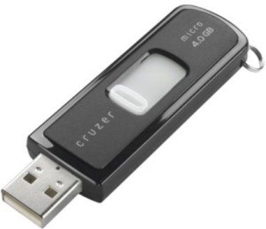 8GB, 16GB, 32GB of data and more can be stored on these small flash drives which can be used on computers and HDTVs. Keep songs, videos, photos and files at hand, easily carried in a pocket. Connects with the built-in USB connector. USB Features - Simply plug it in - everything configures automatically. True Plug-and-Play! Connect and reconnect peripherals without rebooting your PC. Plugable USB 2.0 10 Port Hub (with Power Adapter) There are 8 fixed ports on this hub and two ports that swivel out. There are 6 fixed ports on one side and 4 ports on the other. The side with 4 has the two swivel ports. Initially the Universal Serial Bus (USB) was designed to connect peripheral devices, such as keyboards and mice, to PCs. However, USB has proven useful for many other applications. The USB 1.1 specification specified a maximum throughput of 12 megabits per second (Mb/s), but later USB developments increased the potential speed to 480 megabits per second and more. USB’s main attraction is that it makes adding peripherals to your computer incredibly easy. It enables you to connect peripherals to the outside of the computer so you don't have to open your PC. Laptops benefit even more because generally the case cannot be opened. Laptops have many USB ports so multiple devices can be connected to the computer. Introduced in 1995, the USB standard was developed by industry leaders including DEC™, IBM®, Intel®, Microsoft®, and Compaq®. Most PCs and peripherals available today feature at least one USB connection. Peripherals can include everything from modems to joysticks. Windows® 95 Rev. B, Windows 98, Windows 2000, Windows Me, Windows XP, Windows Vista, Windows 7, Windows 8 and Mac® OS 8 and higher support USB. A USB peripheral simply plugs into the port and works. You don’t need to install a card; you don’t even need to turn off your computer—USB devices are completely hot-swappable. Because USB also distributes power, many USB devices don’t require a separate power supply, although a bus-powered device must be attached upstream to either a host PC or a powered hub. USB configuration happens automatically, so built-in USB means you don’t have to fiddle with drivers and software when adding most peripherals. USB host controllers automatically detect when peripherals are connected to or disconnected from a port. The controllers manage and control the driver software and bandwidth required by each peripheral. They even allocate the right electrical power to each peripheral. USB uses a tiered star topology, meaning that USB devices called hubs can serve as connection ports for other USB devices. Only one device needs to be actually plugged into your PC. USB supports hubs that can be either standalone or embedded within some other device such as a keyboard or disk drive. A single USB port can support up to 127 devices. USB 1.1, has two data rates: 12 Mbps for devices such as disk drives that need high-speed throughput and 1.5 Mbps for devices such as joysticks that need much lower bandwidth. In
2002, a newer specification, USB 3.0 USB 3.0 "Superspeed" (2009) is the second major revision of the USB standard. USB 3.0 has transmission speeds of up to 5 Gbit/s, which is 10 times faster than USB 2.0 (480 Mbit/s). USB 3.0 adds new cable connectors partially for backwards compatibility of USB 2.0. The connectors have dual hookups. One for USB 2.0 and one for USB 3.0. USB 3.0 adds five wires for a total of nine wires in the connectors and cabling and utilizes a unicast dual-simplex data interface that allows data to flow in two directions at the same time; an improvement over USB 2.0’s unidirectional communication. USB 3.0 Standard-A receptacles are backward-compatible with USB 2.0 but add new pins for USB 3.0 signals. The new Standard-B and Micro-AB receptacles are also backward-compatible. The USB
host automatically detects when a new device has been added, queries
for device identification, and appropriately configures the drivers.
Due to the bus topology, up to 127 devices can run concurrently on one
port. Conversely, the classic serial port supports a single device on
each port. By adding hubs, more ports can be added to a USB host,
creating connections for more peripherals.
USB supports three data rates. A Low Speed rate of 1.5 Mbit per second that is mostly used for Human Input Devices (HID) such as keyboards, mice, joysticks and often the buttons on higher speed devices such as printers or scanners. USB has a Full Speed rate of 12 Mbit per second. Full Speed was the fastest rate before the USB 2.0 specification and many devices fall back to Full Speed. Full Speed devices divide the USB bandwidth between them in a first-come first-serve basis and it is not uncommon to run out of bandwidth with several isynchronous devices. All USB Hubs support Full Speed. USB 2.0 added a Hi-Speed rate of 480 Mbit per second. Not all USB 2.0 devices are Hi-Speed. A USB device should specify the speed it will use by correct labeling on the box it came in or sometimes on the device itself. Hi-Speed
devices should fall back to the slower data rate of Full Speed when
plugged into a Full Speed hub. Hi-Speed hubs have a special function
called the Transaction Translator that segregates Full Speed and Low
Speed bus traffic from Hi-Speed traffic. The Transaction Translator in
a Hi-Speed hub (or possibly each port depending on the electrical
design) will function as a completely separate Full Speed bus to Full
Speed and Low Speed devices attached to it. This segregation is for
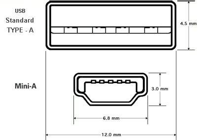
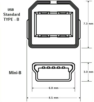
bandwidth only; bus rules about power and hub depth still apply. An even newer USB standard, USB On-The-Go (USB OTG) is also being developed. USB OTG enables devices other than a PC to act as a host. Use it to connect portable equipment, such as PDAs, cell phones, and digital cameras, to each other without using a PC host. USB connectors: Type A, Type B, Mini B, Mini A, Micro-B. USB 1.1 specifies the Type A and Type B. USB 2.0
specifies the Type A, Type B,
and Mini B. The Mini A connector was developed as part of the USB OTG
specification and is used for smaller peripherals, such as cell phones.
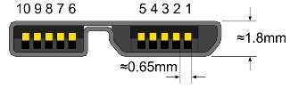
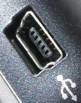
5) USB 2.0 Micro-B The micro-B is flatter than the mini-B, and was designed to work better with smaller form-factor devices. 6) USB 3.0 B-Type 7) USB 3.0 Micro-B
The USB 3.0 micro-B connector
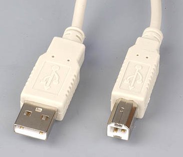
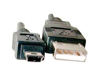
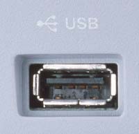
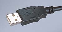
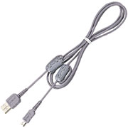 USB logo symbol found on cables and jacks designating USB interface. Cable USB Type A to Type Mini-B ( male/male ) Connects your computer to any USB device with Type Mini B female port. This cable allows you to connect peripherals such as digital cameras, MP3 players, and storage drives. It is USB 2.0 certified and supports USB speed up to 480Mbps. (Connectors: Type A Male to Mini B Male) 6 ft cable. 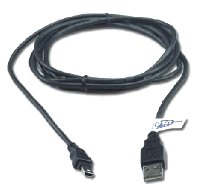 Cable USB Type A to Type B ( male/male ) Connects your computer to any USB device with Type B female port. It allows you to connect peripherals such as printers, scanners, and storage drives. Supports USB speeds up to 480Mbps. (Connectors: Type A Male to B Male) 6 ft cable shown. 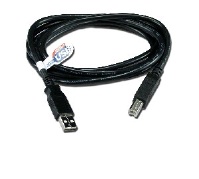 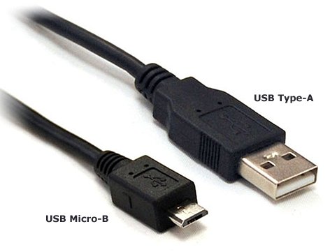 USB 2.0 Type-A and USB 2.0 Micro-B 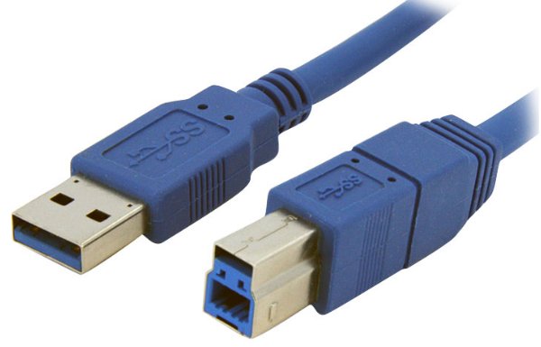 USB 3.0 Type-A and USB 3.0 Type-B USB 3.0 cables are bright blue and have SS for Superspeed with the logo. A USB 3.0 Type-B male cable connector cannot fit into a USB 2.0 device port. But the 3.0 Type-A male connector will fit into a USB 2.0 host port. So using a 3.0 device with a 2.0 host is possible if you use the 3.0 cable. Your speed will not be 3.0 however, just 2.0 speed because the 2.0 host has only a USB 2.0 controller. The host would need a USB 3.0 controller onboard also in order to get USB 3.0 speeds. |
USB 2.0 Cables
| Pin | Name | Description |
| 1 | VCC | +5 VDC |
| 2 | D- | Data - |
| 3 | D+ | Data + |
| 4 | GND | Ground |
|
USB signals are transmitted on a twisted pair of data cables, labeled D+ and D-. These collectively use half-duplex differential signaling to combat the effects of electromagnetic noise on longer lines. Contrary to popular belief, D+ and D- operate together; they are not separate simplex connections. The USB connector
provides a single 5 volt wire from which connected USB devices may
power themselves. A given segment of the bus is specified to deliver up
to 500 mA. This is often enough to power several devices, although this
budget must be shared among all devices downstream of an un-powered
hub. A bus-powered device may use as much of that power as allowed by
the port it is plugged into. Bus-powered hubs can continue to
distribute the bus provided power to connected devices but the USB
specification only allows for a single level of bus-powered devices
from a bus-powered hub. This disallows connection of a bus-powered hub
to another bus-powered hub. Many hubs include external power supplies
which will power devices connected through them without taking power
from the bus. Devices that need more than 500 mA or higher than 5 volts
must provide their own power. • See over 100 audio video hookup diagrams • Audio Video Cable Types • VCR hookup to PC, VHS to DVD Power usage:Bus-powered
hubs: Draw Max 100 mA at
power up and 500 mA normally. Voltage:
Cable:Shielded: Non-shielded: |
| Power Gauge | Max length |
| 28 | 0.81 m |
| 26 | 1.31 m |
| 24 | 2.08 m |
| 22 | 3.33 m |
| 20 | 5.00 m |
| Pin | Name | Cable color | Description |
| 1 | VCC | Red | +5 VDC |
| 2 | D- | White | Data - |
| 3 | D+ | Green | Data + |
| 4 | GND | Black | Ground |
| The USB 2.0 spec was developed by a team of seven industry-leading companies, collectively named the USB 2.0 Promoter Group. The group consists of Compaq, Hewlett Packard, Intel, Lucent, Microsoft, NEC, and Philips. |
Since Hi-Speed USB 2.0 is now about the same speed as IEEE 1394a, don't they compete? |
| No. Hi-Speed USB 2.0 is expected to become ubiquitous on all PC platforms because it is more easily integrated into the core chipsets, at which time it will become the preferred connection for PC peripherals. IEEE 1394 (Firewire, i.Link) on the other hand, targets audio/video consumer electronic devices such as digital camcorders, digital VCRs, DVDs, and digital televisions (HDTV). Therefore, the two connections will differ primarily in application focus. USB 2.0 and IEEE 1394, while offering similar data rates, primarily differ in terms of application focus. The USB 2.0 Promoter group expects USB 2.0 to be the preferred connection for most PC peripherals, whereas IEEE 1394's primary target is audio/video consumer electronic devices. Both USB 2.0 and IEEE 1394 are expected to coexist on many consumer systems in the future. |
| USB
2.0 Specification The USB 2.0 specification divides USB devices into three categories based on transfer rates:
The primary differences between USB 1.1 and 2.0 specifications are the addition of lower-latency 480 Mb/s transfers and improved host software specifications. USB 1.1 compliant devices will not become obsolete because all USB 1.1 devices are compatible with the USB 2.0 standard (they are classified as full- or low-speed devices). Visit: http://www.usb.org/
Universal Serial Bus (USB) One of the reasons that USB was implemented was to replace existing serial and parallel ports on computers. USB has several advantages for this application, which is why it has been included in most of the new PCs that have been shipped since Windows 98 was released in late June of 1998:
USB Implementers Forum, Inc. is a non-profit corporation formed by a group of companies that developed the initial USB specification. Among their activities is the development of a testing and certification program for compliance with the USB specification. Before a device can use the USB logo or icon, it must undergo rigorous testing and be certified as USB compliant. While this compliance testing goes a long way toward ensuring device compatibility, there are no guarantees, however, that all USB certified devices will be able to work together compatibly over a particular USB bus. This is not only because of differences in interpreting and implementing the USB standard and failure by some manufacturers to adhere to the standards, but also because of the rapid development of technology itself. For example, because of the limited bandwidth of the USB 1.x standard, care must be exercised when combining devices compliant with that specification where data receipt is time-sensitive -- such as several devices on one bus that all transfer video simultaneously. There are several different editions of the USB standard that have been released:
Windows 95 (and earlier versions of Windows) has no USB support, however a sub-release of Windows 95 (OEM Service Release 2) was issued to computer manufacturers and it added somewhat limited support for the USB protocol. Windows 98 added additional support and fixed some problems that were in the 95 OEM Service Release 2. Windows 98se (98 second edition) released in early June of 1999 had more robust support for USB. Both Windows 2000 and Windows Me released in early 2000 added additional features. Apple Computer's OS 9.0.4 was released late summer of 2000 and added much better support for USB for the Mac. Many problems associated with USB can be solved by using the latest version of the appropriate operating system. In this article, the term USB includes all the above revisions as a general protocol. However, the operating details described below refer to USB 1.x (both USB 1.0 and 1.1) unless otherwise specified. Also, when a "device" is mentioned here, it is referring to a USB-compliant peripheral. With the release of Windows XP and the computers that can run it, USB is standard and devices can be connected and hot-plugged with automatic recognition by the Operating System. How USB WorksUSB uses a four-wire cable interface. Two of the wires are used in a differential mode for both transmitting and receiving data, and the remaining two wires are power and ground. The source of the power to a USB device can come from the host, a hub, or the device can be "self powered." There are two different connector types on each end of a USB cable. One of these connectors is for upstream communications, and the other for downstream. Each cable length is limited to about 5 meters. USB has four types of communication transfer modes:
In interrupt mode, interrupts do not occur in the usual sense. As in control mode, the host has to initiate the transfer of data. Interrupt mode works by the host querying devices to see if they need to be serviced. Bulk mode and isochronous mode complement each other in a sense. Bulk mode is used when data accuracy is of prime importance, but the rate of data transfer is not guaranteed. An example of this would be disk drive storage. Isochronous mode sacrifices data accuracy in favor of guaranteed timing of data delivery. An example of this would be USB audio speakers. The PC host typically has connections for two external USB ports. Each of these two connectors on the PC is actually a connection to a separate root hub inside the PC. If either of the two root hubs needs to have more than one device connected to it, a downstream USB hub is required to expand connections. Hubs are used to add to the number of devices that can be connected to one USB port. They can be considered to be a repeater of sorts and also a controller. When a device is connected downstream of a hub, the hub does the connect detection of the new device and notifies the host. Hubs can be inside the device itself -- for example, in a keyboard that may have an additional two downstream USB connectors for additional devices. A hub can have a combination of high and low speed devices connected to it, up to a maximum of four additional hubs downstream from itself. A hub's upstream port to the PC must be high speed. The hub acts as a traffic cop, handling communication to downstream devices as either high or low speed. A hub can ignore a downstream device that is not behaving properly. Hubs can be either self-powered or receive power from the USB bus. USB 1.x hubs support both low and high-speed data transfers. There are several hardware requirements for devices that are placed on the USB bus. Five volts is the nominal supply voltage on the bus. A device that requires 100mA or less can be powered from the host or any hub, provided that the total available power hasn't already been exhausted by other devices. A device on the bus can draw up to 500mA from it. However, not all USB hosts (especially a battery powered PC) or bus-powered hubs will allow a device to draw more than 100mA from the bus. For this reason, a USB device that draws more than 100mA should, in most cases, be self-powered . A device tells the host how much current is required for its operation. Self-powered devices usually get their power from a separate power supply or batteries. A battery-powered device plugged into the bus can get its power from the bus if it meets the tests above, and it can then switch back over to battery power when it is disconnected from the bus or when the host is shut down. When a device is in suspend mode, it cannot draw any more than 500uA from the bus if it is bus-powered. Also, if a device has not seen any activity on its bus in 3 mS, it needs to go into suspend mode. A host can initiate a resume command to a device that is in suspend mode. A device can also issue a remote wakeup to an inactive host to make it active. All devices have endpoints, which are memory buffers. An endpoint can be as simple as an addressable single register, or it can be a block of memory that is used to store incoming and/or outgoing data. There may be multiple endpoints inside a device. Each device has at least one endpoint -- "endpoint 0"-- which is used as a control endpoint. It must be able to both send and receive data, but can only communicate in one direction at a time. Typically, when a device receives data such as an Out or Setup command from the host, this data is stored in the endpoint and the device's microprocessor is interrupted and works on this data. When a device receives an In command that is addressed to it from the host, data for the host that is stored in the endpoint is sent to the host. The host is considered to be the master in most all cases. One exception is when a device issues a remote wakeup to the host as discussed above. There are time limits for both the host and device to respond to each other. For example, if the host requests data from a device using an In command, the device must send the data back to the host within 500mS, in some cases. Depending on the transaction type, the host and/or the device may respond to data received with an acknowledgement. Data transfer involves quite a bit of error-checking and handshaking. The different types of data packets sent and received use different ways to verify correct data transfer. A logical connection link needs to be set up between the host and a device before a transaction can occur. This connection is referred to as a Pipe. It is set up as soon as possible after a host has recognized a device as being connected. When the host responds to a connect signal from the device, one of the parameters that is sent to the host is the device's required data transfer type and speed. The host can refuse to establish a Pipe if the host does not have enough bandwidth to support the device's request or if its power requirements cannot be met. The device at its discretion can lower its requested data rate and try again until the host accepts it and initiates a Pipe. When a device is connected, it also sends to the host descriptor information on the types of endpoints in the device, the type of data transfer it uses, size of data packets, endpoint addresses within the device, and if used, the time required between data transfers. The following describes a typical data flow for a device when it is initially plugged into a host's bus while the host is active. Remember that the host has an internal USB hub, and additional hubs may be connected downstream from the host's hub.
USB On-The-Go USB On-The-Go icon USB On-The-Go (OTG) allows two USB devices to talk to each other without requiring the services of a personal computer. USB OTG retains the standard USB host/peripheral model, where a single host talks to USB peripherals. OTG introduces the dual-role device (DRD), capable of functioning as either host or peripheral. Part of the magic of OTG is that a host and peripheral can exchange roles if necessary. To add OTG dual-role capability, the transceiver must be augmented to allow the OTG device to function as either host or peripheral. Before OTG, the concept
of an embedded host was already established in the USB world. Instead
of duplicating the full UHCI/OHCI USB controllers and drivers built
into personal computers, most embedded host chips provide limited
hosting capabilities. This makes them better suited to the embedded
environment than to the PC with its huge resources and infinite
capacity for drivers and application software. Wireless USB is the new wireless extension to USB that combines the speed and security of wired technology with the ease-of-use of wireless technology. Wireless connectivity has enabled a mobile lifestyle filled with conveniences for mobile computing users. Wireless USB will support robust high-speed wireless connectivity by utilizing the common WiMedia MB-OFDM Ultra-wideband (UWB) radio platform as developed by the WiMedia Alliance. UWB technology offers a solution for high bandwidth, low cost, low power consumption, and physical size requirements of next-generation consumer electronic devices.
Columbia ISA Audio Video Empowering consumers through information Columbiaisa@yahoo.com |