|
|
|
• Car Stereo Systems • Smartphone integration in car stereo systems Car Audio Installation There are all kinds of car audio setups. The most simple install is replacing a factory AM/FM radio/CD player with a new after-market stereo. The new unit may have everything the old unit had plus extras such as iPod/USB hookup, MP3 capability, iPhone calling, Bluetooth, HD radio or satellite radio, DVD player, navigation and more. For a simple head unit replacement you will still use your existing speakers and existing wiring inside the car. You are just replacing the head unit. More complex installs involve adding power amplifiers, subwoofers, additional speakers and wiring. For these installs you may want to consult a pro install shop or you could do it yourself if you have experience with electrical, audio/video setups, wiring and tools. SIMPLE INSTALL - REPLACE HEAD UNIT. What you need: a new car stereo with all the features you want, which is also called a head unit, wire strippers, electrical tape, a screwdriver set, socket wrench, and wire cutters/crimper. Also you may need a wiring harness adapter, butt connectors or a soldering iron and solder. STEP by STEP 1) Buy a new stereo head unit. Purchase one that fits correctly where your old factory unit was located. You may need to use the old mounting brackets off the factory head unit. In addition, when purchasing a stereo you might want to get a wiring harness which is specific for your new stereo and your vehicle's make, model and year. These are available for most car makes and models for years going back 10 years or more. Car audio head units come in a single DIN size about 7 in. wide by 2 in. tall and the double DIN size, 7 in. wide by 4 in. tall. You may need to buy an install kit for your unit if the height sizes do not match up. Usually a double DIN opening in the dash can be used for a single DIN head unit by using a tray or other covering on the bottom 2 in. You also need to consider the depth. Usually the depth of the unit will fit into the dash but measure to be sure. Many head units appear to be wider or taller than the standard DIN sizes due to the front panel faceplate but the actual box of the hardware containing the CD player/radio, for example, is standard DIN size. Install kits specific for your car are available to flush the new faceplate with the dash. 2) Make sure the engine is turned off. Disconnect the negative (black) car battery cable. Never work on any part of your car's electrical system with the car battery connected, as the electrical shock could be fatal. REMOVE OLD RADIO 3) Depending on your exact vehicle, the removal process varies. Generally you must take apart the dash components to get at the radio. Remove the dash panel covering surrounding your car stereo. Typically you just pry a plastic frame off using a flathead screwdriver. Some cars may not have a frame covering because the stereo is flush with the dash. Unscrew and remove your old stereo (head) unit. Usually four screw bolts hold the head unit in place. Remove these and pull unit partially out. On the back of the unit there will either be a batch of individual wires or a plug connecting a lot of wires. If you find a bunch of wires, do not take them apart just yet. You will need to do them one at a time. Some units have several plugs with multiple wires. Also there may be an antenna wire connected to the unit. This needs to be removed as well as the wiring harness in order to disconnect the head unit. Example of required process to remove radio head unit: Newer cars may have a more complicated removal process than older cars. 2007-2008 Toyota Camry Factory Radio Removal 1. Remove the top center air vent assembly. It comes straight out but there are clips along the top and bottom seams. Disconnect harness. 2. Remove shift knob and the shift console cover by gently pulling up to release clips. Don't break any of the plastic snap pieces. 3. Remove shift console top cover trim by gently pulling up. Note harness. 4. Remove the vertical trim columns to the right and left of the storage box (that is below the climate controls) by pulling straight out - again releasing clips. 5. The space behind the vertical trim columns will reveal screws that hold down the storage box. Remove the screws and partially pull out the box. 6. (Steps 2 thru 5 are necessary to gain access to two bottom bolts securing the bottom of the head unit/climate control assembly) Remove the two bottom bolts. 7. (Step 1 gains access to two top bolts securing the top of the head unit/climate control assembly) Remove the two top bolts. 8. Slide head unit/climate control assembly out. Disconnect wiring harnesses. Before you start - disconnect the negative battery terminal and set your shifter as far back as possible. 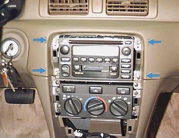 4 Screw bolts holding stereo in dash. Remove in order to pull factory stereo from the car's dash. Use a socket wrench.  Old head unit removed. Disconnect wiring harness(s) and pull out antenna wire. Dash should look like the above image. INSTALLING NEW HEAD UNIT 4) Now you must decide how you are going to wire up the new head unit. 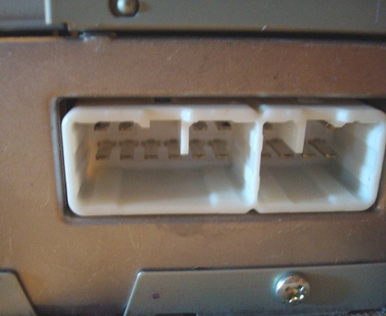 The above image shows the head unit's male connection pins for power, ground and the speakers. Before, your old head unit was connected using the female factory wiring harness directly to the factory head unit. However, with your new head unit, you probably have a different pin configuration and your old factory wiring harness will not be compatible, physically or electrically. Therefore, you have to wire up the car's existing wires for power, ground and speakers to the new head unit's pin setup. This can be done wire by wire manually using butt connectors or soldering or you can use an adapter to plug into the factory wiring harness. 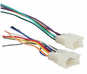 Adapter harness plugs into factory wiring harness. This is the recommended method but you could just cut off your factory harness and attach each wire manually using solder, butt connectors or just electrical tape over twisted wire connections. You still need a chart showing what each wire is used for so you know which wires to connect. This information is available online or in your vehicle service manual. The following is one example.
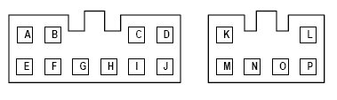 Wiring Harness Pins 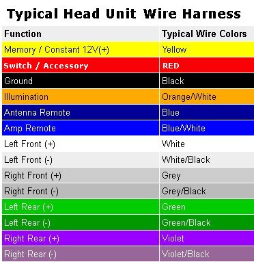 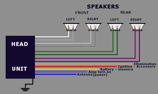 Connect the ground wire (black) to anything metal on the car. Make sure it's a good, solid piece of metal actually connected to the chassis. And to connect, its best to put a small ring terminal on the end of the wire and use a sheet metal screw to hold it down. May have to drill a small pilot hole. This will be the most solid connection. Use a "ring terminal" and "star washer". www.wiringproducts.com www.almabolt.com You can solder and shrink wrap your connections. It's not hard, and it'll be worth it to be certain things won't come undone. If you just twist and tape, eventually things slowly loosen and can come undone. Also very hot or cold temps can make the electrical tape either lose it's stickiness or just slide off. • How to solder wires with shrink wrap You'll get familiar with wire colors. They are mostly standard. The yellow wire always supplies power to the head unit so that it can keep it's memory for radio staion presets, base & treble settings, etc. The red wire is powered only when the key is turned on and gives power to the head unit. The orange wire is powered when you have your parking lights or headlights on, it tells the head unit to change it's coloring or dim or whatever feature the unit has so it's brighter in the daytime and dimmer at night. The blue wire sends power from the head unit downstream to tell amplifiers to turn on. 5) Plug your new wiring harness into the connector, if you were able to purchase one. This wiring harness will then plug into the backside of your new car stereo. If you were able to do this, then you can skip steps 6-8. 6) You will need to connect each of the wires manually if you did not buy a wiring harness. Connect positive wires from each of your speakers to positive connectors on the backside of your stereo first. Next, connect negative wires from each of your speakers to negative connectors on the stereo. If you find only one wire coming from each speaker this means that they have been grounded at the chassis. If this is the case, new speaker wiring must be installed. 7) Connect the -/black (ground) wire on the stereo to a bolt or screw near where the stereo is mounted within the dash. This attachment must be made to metal, not fiberglass or plastic. 8) Connect both +/red ignition power wires and the 12 constant wires to the new radio. Refer to the installation manual for correct placement of these wires. 9) You should now have a single connecter which can be hooked to the proper wires in your vehicle, either through the new connection made in steps 6-8 or from your wiring harness. 10) Slide the new stereo into your mounting bracket, which should have been included with purchase. In some cases, you may need to use your old bracket from your original stereo. 11) Plug the wiring harness connector into the backside of your new radio. You should see one, single wire hanging unaccounted for, coming from your old system. This wire is your antenna. Plug this wire into your new stereo unit. You may also see a power antenna wire, which must be connected as well. 12) Slide the stereo into dash slot. Test it before screwing it in. Reconnect your battery cable. Start your engine to power up the stereo. Turn on some music and listen for the performance of each speaker. If everything seems to be working, bolt your new stereo into place and replace your dash cover(s). This harness is used to wire up to the aftermarket radio harness and plug into the OEM (original equipment manufacturer) wire harness behind radio for 1987-2008 Toyota models. Provides power to aftermarket radio Allows speaker connection Fits into factory plug WIRE CONNECTIONS There are 3 ways to attach wires together: 1. Twist bare ends together and wrap parallel to the wire, then wrap with good electrical tape. When all wires are taped, then tape all together with electrical tape into a bundle. 2. Butt connectors and a crimping tool. 3. Solder and wrap with electrical tape. Butt / Wire Connectors Butt wire connectors, sometimes known as butt splices, securely fasten two wires with a crimp connection. Butt connectors are available either insulated or non-insulated. 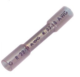 
These heat shrinkable, nylon butt connectors feature an all weather seal. Installation is simple. Select the correct butt connector for the wire gauge, strip wires and insert into crimp barrel, crimp connection using the correct tool, then apply heat until the tubing shrinks and adhesive/sealant flows making water-tight connection. 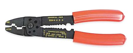 Wire cutter/stripper and crimping tool SOLDERING WIRES 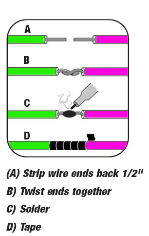 Vehicle specific wire colors: 1996 Cadillac Fleetwood Car Stereo Radio Wiring Diagram Radio Constant 12V+ Wire: Orange Radio Ignition Switched 12V+ Wire: Yellow Radio Ground Wire: Black Radio Illumination Wire: Gray Radio Antenna Trigger Wire: Pink Left Front Speaker Wire (+): Tan Left Front Speaker Wire (-): Gray Right Front Speaker Wire (+): Light Green Right Front Speaker Wire (-): Dark Green Left Rear Speaker Wire (+): Brown Left Rear Speaker Wire (-): Yellow Right Rear Speaker Wire (+): Dark Blue Right Rear Speaker Wire (-): Light Blue 2006 Cadillac DTS Car Radio Wiring Diagram Car Radio Battery Constant 12v+ Wire: Dark Green/Tan Car Radio Accessory Switched 12v+ Wire: N/A Car Radio Ground Wire: Black Car Radio Illumination Wire: N/A Car Stereo Dimmer Wire: Yellow Car Stereo Antenna Trigger Wire: Pink Car Stereo Amp Trigger Wire: Pink Car Stereo Amplifier Location: Behind driver side rear seat in trunk. Left Front Speaker Positive Wire (+): Tan Left Front Speaker Negative Wire (-): Dark Green/Red Right Front Speaker Positive Wire (+): Light Green/White Right Front Speaker Negative Wire (-): Light Green Left Rear Speaker Positive Wire (+): Brown/White Left Rear Speaker Negative Wire (-): Brown Right Rear Speaker Positive Wire (+): Dark Blue Right Rear Speaker Negative Wire (-): Tan/Red 2005 Cadillac Escalade EXT Car Audio Wire Color Codes Car Radio Battery Constant 12v+ Wire: Orange Car Radio Accessory Switched 12v+ Wire: Run a wire to the steering column and use the orange wire in the ignition switch harness. Car Radio Ground Wire: Black/White Car Radio Illumination Wire: N/A Car Stereo Dimmer Wire: Brown/White Car Stereo Power Antenna Trigger Wire: N/A Car Stereo Amp Turn-On Trigger Wire: N/A Left Front Speaker Positive Wire (+): Tan Left Front Speaker Negative Wire (-): Gray Right Front Speaker Positive Wire (+): Light Green Right Front Speaker Negative Wire (-): Dark Green Left Rear Speaker Positive Wire (+): Brown Left Rear Speaker Negative Wire (-): Yellow Right Rear Speaker Positive Wire (+): Dark Blue Right Rear Speaker Negative Wire (-): Light Blue Car Subwoofer Speaker Positive Wire (+): N/A Car Subwoofer Speaker Negative Wire (-): N/A 2001 Cadillac Seville Car Radio Installation Instructions Car Radio Battery Constant 12v+ Wire: Orange Car Radio Accessory Switched 12v+ Wire: Red Car Radio Ground Wire: Black Car Radio Illumination Wire: Yellow/Black Car Stereo Dimmer Wire: Brown Car Stereo Antenna Trigger Wire: N/A Car Stereo Amp Trigger Wire: N/A Car Stereo Amplifier Location: Mounted To Back Of Rear Seat Behind Trim Left Front Speaker Positive Wire (+): Tan Left Front Speaker Negative Wire (-): Gray Right Front Speaker Positive Wire (+): Light Green Right Front Speaker Negative Wire (-): Dark Green Left Rear Speaker Positive Wire (+): Brown Left Rear Speaker Negative Wire (-): Yellow Right Rear Speaker Positive Wire (+): Dark Blue Right Rear Speaker Negative Wire (-): Light Blue 2001 Toyota Camry Car Radio Wire Diagram Car Radio Battery Constant 12v+ Wire: Blue/Yellow Car Radio Accessory Switched 12v+ Wire: Gray Car Radio Ground Wire: Brown Car Radio Illumination Wire: Green Car Stereo Dimmer Wire: N/A Car Stereo Antenna Trigger Wire: N/A Car Stereo Amp Trigger Wire: Pink/Blue Car Stereo Amplifier Location: Located to the right of the glovebox behind the passenger side of the dash. Left Front Speaker Positive Wire (+): Pink Left Front Speaker Negative Wire (-): Violet Left Front Tweeter: Powered by the same wires as the left front speaker. Right Front Speaker Positive Wire (+): Light Green Right Front Speaker Negative Wire (-): Blue Right Front Tweeter: Powered by the same wires as the right front speaker. Left Rear Speaker Positive Wire (+): Black Left Rear Speaker Negative Wire (-): Yellow Right Rear Speaker Positive Wire (+): Red Right Rear Speaker Negative Wire (-): White 2002 Toyota Tundra Car Stereo Wire Diagram Car Radio Battery Constant 12v+ Wire: Blue/Yellow Car Radio Accessory Switched 12v+ Wire: Gray Car Radio Ground Wire: Brown Car Radio Illumination Wire: Green Car Stereo Dimmer Wire: N/A Car Stereo Antenna Trigger Wire: N/A Car Stereo Amp Trigger Wire: N/A Left Front Speaker Positive Wire (+): Pink Left Front Speaker Negative Wire (-): Violet Right Front Speaker Positive Wire (+): Green Right Front Speaker Negative Wire (-): Blue Left Rear Speaker Positive Wire (+): Black Left Rear Speaker Negative Wire (-): Yellow Right Rear Speaker Positive Wire (+): Red Right Rear Speaker Negative Wire (-): White 2005 Toyota Camry Car Stereo Wiring Diagram Car Radio Battery Constant 12v+ Wire: Blue/Yellow Car Radio Accessory Switched 12v+ Wire: Gray Car Radio Ground Wire: Brown Car Radio Illumination Wire: Green Car Stereo Dimmer Wire: N/A Car Stereo Antenna Trigger Wire: N/A Car Stereo Amp Trigger Wire: Pink/Blue Car Stereo Amplifier Location: Located to the right of the glovebox behind the passenger side of the dash. Left Front Speaker Positive Wire (+): Pink Left Front Speaker Negative Wire (-): Violet Left Front Tweeter: Powered by the same wires as the left front speaker. Right Front Speaker Positive Wire (+): Light Green Right Front Speaker Negative Wire (-): Blue Right Front Tweeter: Powered by the same wires as the right front speaker. Left Rear Speaker Positive Wire (+): Black Left Rear Speaker Negative Wire (-): Yellow Right Rear Speaker Positive Wire (+): Red Right Rear Speaker Negative Wire (-): White Car Audio & Electronics GM Car Radios Delco Radio Wiring Use harness adapters in case you need to plug the original radio back in. American-made GM products are made with Delco electronics. Standard GM radios, whether they were installed in Chevy, Cadillacs or GMC trucks, are all Delco radios with a standard set of plastic plugs and wire colors. Models up to 1989 or 1990 have a different set of plugs and color codes from models manufactured subsequently. Instructions Older (Up to 1989 to 1990) Delco Radio Wiring 1 Locate three plastic plugs fanned out of a single harness bundle. Plug colors are blue, white and black. Each plug has four pin positions and may have four corresponding wires. All plugs are almost square, and have alignment ridges that guide insertion to specific slots at the rear of GM radios. A fourth, smaller and flatter plug may accompany the other three. This plug is usually connected for electronic preset and clock memory. 2 Locate the following colors on the blue plug for rear speaker connections: Right: Negative=light blue, Positive=dark blue Left: Negative=yellow, Positive=brown. 3 Locate the following colors on the white plug for front speaker connections: Left: Positive=tan, Negative=light gray Right: Positive=light green, Negative=dark green 4 Locate the following colors on the black plug for power connections: Yellow=12 volts ignition, black=ground, gray=illumination, pink, if present, activates a power antenna. The small, flat plug has an orange wire to a 12-volt battery for preset and clock memory. 5 Trace each wire through the adapter plugs, strip the ends applicable to the stereo you are installing and use crimp connectors to mate the wires with the stereo's output wires. Use a test light to test power and illumination connections. Use a multimeter to test for ground wire continuity and speaker connections. Newer (1990 and up) Delco Radio Wiring 1 Find a harness bundle with two four-connection plugs for speakers, and one six-connection plug for power connections. 2 Find the following colors on the front-speaker, four-connection plug: Light gray=left negative, tan=left positive. Light green=right negative, dark green=right positive. 3 Find the following colors on the rear-speaker, four-connection plug: Light blue=right negative, dark blue=right positive. Yellow=left negative, brown=left positive. 4 Find the following colors on the six-connector plug: Yellow=12 volts switched Black=ground Gray=dimmable illumination Pink=power antenna activate Orange=12-volt battery wire for preset and clock memory 5 Trace each wire through the adapter plugs, strip the ends applicable to the stereo you are installing and use crimp connectors to mate the wires with the stereo's output wires. Use a test light to test power and illumination connections. Use a multimeter to test for ground wire continuity and speaker connections. General Motors Radio Wire Harnesses Car Stereo Radio Unlock a Radio All information on this site is provided "as is" without any warranty of any kind, expressed or implied, including but not limited to fitness for a particular use. Any user assumes the entire risk as to the accuracy and use of this information. Verify all wire colors and diagrams before applying any information. Columbia ISA Audio Video Empowering consumers through information columbiaisa@yahoo.com |