Connect DTV converter with VCR, TV, DVD, A/V Receiver
This connection involves two Digital to Analog TV converter boxes to two VCRs, a TV set, a DVD player, an Audio Recorder and an Audio Video Receiver. The Receiver is a 1994 A/V receiver without Dolby Digital 5.1, the VCRs are Hi-Fi stereo and the TV is a 27 inch analog with AV inputs. An outdoor antenna is used to receive digital TV broadcasts.
Components:
o VHF/UHF Antenna
o Two DTV digital to analog converter boxes
o Analog NTSC TV set.
o Standard VHS stereo VCR X 2.
o DVD Player.
o Audio/Video Receiver.
o Stereo Audio Recorder
o Three sets of Audio/Video RCA cables (1-yellow, 1-red & 1-white audio).
o Four RF coaxial cables (RG-6).
o One composite video cable (yellow)
o Two sets analog audio cables (red, white)
TV
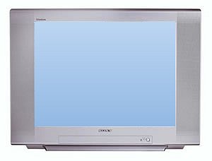
• SONY WEGA 27 inch Trinitron
• built-in stereo speakers
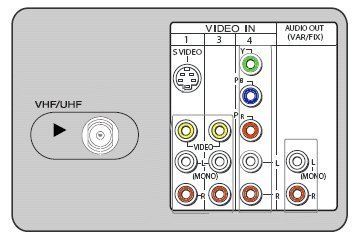
• A/V inputs, including:
• 1 Component video
• 3 composite video (2 rear, 1 front)
• 1 S-video
• RF input for antenna/cable signals
• 1 Audio Out (stereo)
VCR
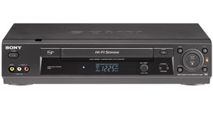
• Standard VHS VCR Hi-Fi Stereo
• RF input; RF output
• Composite audio/video inputs and outputs
• VHF/UHF cable ready tuner
• Video
System NTSC
Connectors
Inputs
Audio/Video Composite - x1 (RCA)
RF Antenna - x1 (Coaxial)
Outputs
Audio/Video Composite - x1 (RCA)
RF (TV Out) - x1 (Coaxial)
Remote Control Yes
Power Requirements 120VAC, 60Hz
Digital to Analog TV Converter box

PHILCO TB100HH9
• RF input; RF Output
• Audio/Video Outputs
• Philco converter box
Audio Recorder/Player
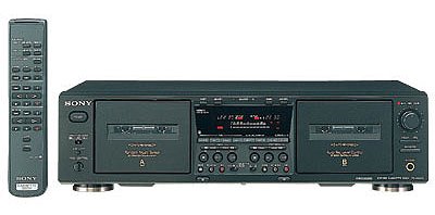
• Left and Right Stereo Inputs for recording audio
• Left and Right Stereo Outputs for playing audio
Audio/Video Receiver
Stereo Audio Inputs/Outputs:
• CD, Phono, Tape1 (play, record), Tape2
Video/Audio Inputs/Outputs
• VCR1 In/Out, VCR2 In/Out, LD In, TV/Sat In, Video In, Monitor Out
Loudspeaker Outputs: Left Front, Right Front, Center, Rear Left, Rear Right
Hook up DIAGRAM - TV, DTV Converter box, VCR, DVD player, A/V receiver, Audio recorder/player
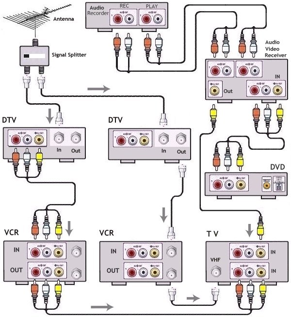
Cables Connections and explanation:
A VHF/UHF antenna is used to receive digital TV broadcasts. The input signal is split using a standard signal splitter. If splitting the signal causes problems with reception, then a signal booster may be required or another solution would be to use two antennas.
1. Connect a RF coaxial cable (RG-6) from each of the splitter Outs to the RF Input (ANT In) on each of the DTV converter boxes.
2. One Converter box will use RF Out and the other will use Audio/Video Outs. Connect RF coaxial cable from DTV box (Out to TV) to VCR RF Ant Input. Connect the other DTV box A/V Out to the A/V inputs on VCR.
3. One VCR will use the RF out to the TV RF input using a coaxial cable while the other VCR will use audio/video OUT to the TV audio/video inputs.
4. The DVD player is connected to the Receiver audio/video input (Video In) Yellow video and red/white audio cables. The receiver's amplifier and loudspeakers can provide a richer sound experience than the TV speakers when playing a DVD movie.
5. Connect a single yellow video cable from the receiver's MONITOR OUT to one of the TV's yellow video IN jacks. This allows the video portion of the DVD movie to be viewed on the TV set.
6. Connect a pair of stereo audio cables from the audio player/recorder PLAY (Out) jacks to the Receiver's audio input jacks (TAPE IN). This allows the audio player to play sound thru the loudspeakers. Connect a pair of stereo audio cables from the audio player/recorder RECORD jacks to the Receiver's TAPE OUT jacks. This allows the audio from the receiver to be recorded on the audio player/recorder.
Why would you want this
configuration?
o To view TV shows from digital TV broadcasts using analog TV.
o To record TV shows to VHS recorder.
o To watch one TV show while recording another on VCR.
o Play recordings to TV.
o Play audio thru receiver.
o Watch DVD-Video.
What can you do with this configuration?
o
Watch TV, record TV shows and play back, watch DVD Video, listen to audio CD.
What settings do you need for this configuration?
The TV, VHS recorder will need to be set to the proper input depending on your source. Select proper input source on the TV to watch DVD or VHS or broadcast TV. Select proper input source on VCR to record TV. The input sources can be selected usually by using the remote control buttons for the respective devices. Buttons such as LINE or VIDEO or AUX or INPUT SELECT or an actual channel such as 93 or 00 or 99 depending on your brand. Consult owner's manual here.
RF cable OUT from Converter box connects to the VCR's Antenna INPUT. When turned OFF the VCR will "Pass-thru" the signal. The converter box usually outputs on channel 3 or 4 via the RF coaxial connection.
When turned ON, the VCR will output on channel 3 or 4 on the RF coaxial cable and also output on the three RCA cables. Set the TV on LINE input to view the VCR output or set the TV to channel 3 or 4 to view output from VCR's RF coaxial connection.
Example of selecting proper line input:
You want to record a VHS tape on the VCR using A/V inputs and view on the TV.
1. Select L1 line input on the VCR to receive the output from the converter box which is using audio/video (3 RCA) outputs.
2. Select line input on the TV for the VCR's input signal.
TV Channels are selected on the DTV converter box using the remote control for the DTV box. The DTV converter box will output on channel 3 or 4 (VHF) using the RF cable connection and output to the 3 RCA cables audio/video line output. The VCR outputs on channel 3 or 4 using the RF cable connection and line output using 3 RCA cables. VCR must be set to channel 3 or 4 if using the RF coaxial connection.
Search Columbia ISA
Google
See
more...
• Input Select on TV and other devices
• Cable hookup digital cable and TV
• Audio Video Connections and cables
• HDMI Versions
• HDTV hookup options
• HDTV basic setup
• See over 100 hookup diagrams
Columbia ISA - Empowering consumers
thru information.
columbiaisa@yahoo.com
|