Your computer contains all the required circuits to operate as designed
but it does not contain every possible function that it is capable of
performing. This is where the add-on or upgrade comes in. You can add functions to
your computer by installing an additional circuit card on the
motherboard.
These circuit cards increase the functionality of the
computer. They are called cards, boards, adapters or controllers but
all these terms mean basically the same thing.
Before buying a card, make sure your computer motherboard has the proper expansion slots available for the install.
Examples of cards you can add to upgrade your computer are graphics, storage expansion, wi-fi capability, expanded sound capability and more.
How To Install a PCI
card in your PC
For those people without computer or electronics experience, the task
of opening up their computer and installing circuit boards may seem
like a daunting prospect. However the job is really not that hard. If
you follow the instructions below and are very careful, you may be
surprised at how well you do. If you would really rather not take on
this job, then have a professional do it for you.
First some history:
In 1984, IBM marketed its PC AT. At that time the CPU, memory, and I/O
bus all shared a common 8MHz clock. This I/O bus became known as the
ISA (Industry Standard Architecture) bus. ISA was a 16-bit interface,
which meant that data could only be transferred two bytes at a time.
More importantly, the ISA bus only operated at 8 MHz and typically
required two or three clock signals to transfer those two bytes of
data. This was not a problem for devices that were inherently slow
(i.e. COM ports, printer ports, sound cards or CD-ROMs), however the
ISA bus was too slow for high performance disk access and display
adapters.
If your computer is old enough, you may look inside on the motherboard
and see ISA slots. They are typically black in color.
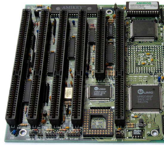
PC ISA - one 8 bit and five 16 bit ISA slots
ISA Slot
Up until about 1999 there were still ISA slots in most PC’s.
In the later years, however, they were only kept for compatibility, so that plug-in cards of the old ISA type could be re-used.
PCI bus 1992 to 2004
PCI stands for Peripheral Component Interconnect. The bus is an Intel product which is used in PC’s and also in other type computers,
as the PCI bus is processor independent. It can be used with all 32-bit and 64-bit processors, and is therefore found in many different computer architectures.
When the ISA bus became mature, other architectures were developed. It
was finally the PCI bus that successfully brought the needed
characteristics to market. Looking on your motherboard inside the PC,
the PCI slots are typically white in color and are shorter than the ISA
slots.
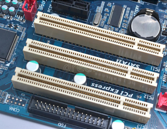
Motherboard with three PCI slots
32 Bit PCI Slot

Two ISA slots and one PCI slot on PC
PCI Express
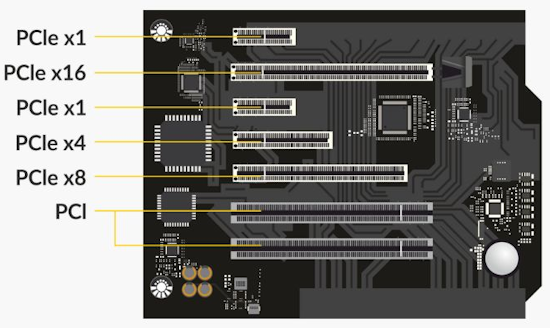
In 2004, a new bus was introduced, the PCI Express or PCIe. Do not confuse a
PCI card with a PCI Express card. There are several versions of PCI
Express with varying slot sizes.
PCI Express stands for Peripheral Component Interconnect Express and is a
standard interface for connecting peripheral hardware to the motherboard on a computer.
PCIe x1: has 1 lane, 18 pins, and 25 mm in length
PCIe x4: has 4 lanes, 32 pins, and 39 mm in length
PCIe x8: has 8 lanes, 49 pins, and 56 mm in length
PCIe x16: has 16 lanes, 82 pins, and 89 mm in length
There have been four versions or revisions of PCI Express over the years 1.0, 2.0, 3.0, 4.0
Installation
What you need is an empty compatible expansion slot in your computer motherboard. There are usually
a few PCI slots on the computer motherboard that line up with some
brackets on the back of the computer. The motherboard is the largest
circuit board in the computer and contains all the required functions
for the computer to operate.
To install a PCI card, turn off and unplug the computer. Before
handling the PCI card, discharge static electricity from your body by
touching a grounded part of your computer chassis. Remove the computer
case/cover with a screwdriver and find an available expansion slot. You will
want to avoid static shock so work in a room with relative humidity of
more than 50% and on a floor without carpeting.
How to open your desktop PC's case.
Tower and desktop style cases.
Before opening the case of your PC, disconnect the power cord. Disconnect all attached devices.
Tower cases
This type of case normally opens up one of two ways, either separate panels on each side or one big sleeve that covers the top and both sides.
Separate panels
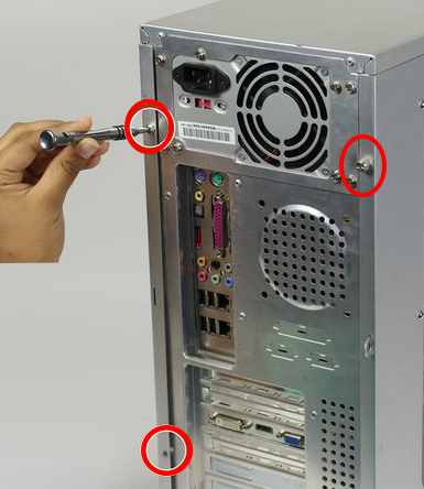
This type of tower case is usually opened by removing 2 or 3 screws on each side of the back of the case.
Alternatively, on quick release type cases there may be one or more slidable latches which when moved in a certain
direction releases the cover from the chassis. The latches should be clearly marked as to which direction releases the cover.
When you have removed the screws or moved the latches you will be able to slide the panels
back to release them from the chassis of the case.
Single sleeve
This type of case is opened by removing 4 or 6 screws (depending on case) from the back.
When all of the screws are removed, slide the whole sleeve backwards, you may have to lift the back end of the sleeve slightly.
Desktop Cases
The most common desktop case is opened by removing 2 screws from each side of the case, and around 3 from the back of the case.
Then slide the cover backwards, you may have to lift the back end of the cover slightly to remove it.
Whichever type of case you have if you are not sure about the way it opens then consult the manufacturer's literature as some manufacturers have special systems for opening their cases. Also, ensure that you will not breaking the terms of your warranty by opening the case as some manufacturers put a security seal which, if broken, can void the warranty.
Once the case is removed, look inside to find the main board with the expansion slots
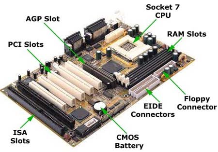
PC Mother Board
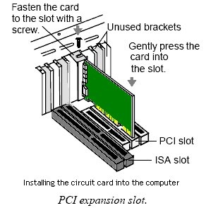
Next, remove the rear covering for the slot you intend to use.
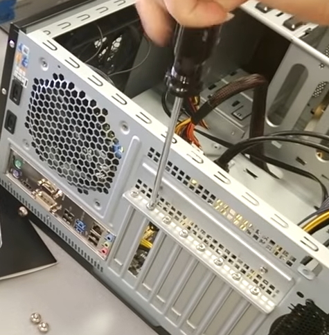
Remove the case bracket that matches up with the expansion slot. These are only there to keep dust out of the internals of the computer.
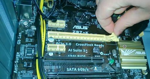
After orienting
the card properly (one end has a gap on the edge) carefully push the card firmly into the slot, avoiding touching the components on
the card. Some cards are more difficult to insert than others so
keep trying but without using excessive force. You can try rocking back
and forth just slightly from end to end and if one end goes in, the
other end should follow.
Insert the bracket screw, and replace the computer cover. You can then
reconnect your computer and turn it on. If your card came with an
installation disk or CD-ROM, insert it and go through the installation
process. When your operating system loads it should recognise the card and either install the drivers automatically, or it will ask you to provide a driver disk (which should have come with the device). You may need to obtain the driver software from the company by going online to their website. If your computer fails to boot-up and just beeps then power-down the system and once again double-check to make sure the card is perfectly aligned and evenly inserted into the slot.
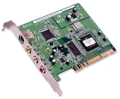
PCI Card for PC
Always check before you buy your PCI card to make sure you have the
proper system requirements that match the PCI card's specifications.
For example, the PCI card may need Windows 2000, ME, or XP so if your
computer is running Windows 98 you have a compatibility problem. Check
inside your computer to make sure you have an empty compatible PCI slot to
accommodate the card you are thinking about buying. Cards should explain the system requirements they need such as will run with Windows 10, 8 and 7.
You can look at the card to see what kind of slot they fit in such as PCIe x1 or PCIe x16. Then check if your computer can accomodate the card.
Cable
Types and connections
For a hookup diagram see:
HDTV
basic setup
See
over 100 Hookup Diagrams
See also:
• PC
stereo hookup
• Windows
Sound Recorder
• VCR
Recording
|