Antenna Hookup over-the-air digital and analog TV
Home wiring for over-the-air digital TV
TV Antenna wiring
Your old TV antenna may be all you need to get digital TV stations, particularly if you live in a large city. However, if you live more than 60 miles from the TV transmitting tower of a local TV station, you may find it difficult to get a signal strong enough to display on your TV. Even if you live well within the limits of TV transmissions, you may need to get a newer TV antenna for the best reception. You may be able to pickup local TV stations with a simple indoor rabbit ears antenna if you are
receiving strong signals from local TV broadcasters.
There is nothing substantially different from the old VHF/UHF antennas and any new, so-called digital or HDTV antenna because the same basic UHF and VHF antennas are used. Yes, you can get High-Definition TV shows with a UHF (VHF) antenna. If you live within 20 miles of the TV tower, you may get away with using an indoor antenna. Any further away, you will most likely need an outdoor antenna.
• TV Antenna Hookup
Important TV antenna concepts to understand
TV antennas are not all the same. There are TV antennas designed to pickup UHF signals and there are TV antennas designed to pickup VHF signals and there are TV antennas designed to pickup both UHF and VHF signals. Some TV antennas are highly directional while others are more non-directional. It is important to know where your TV station's transmitting tower is in relation to your antenna's location.
www.tvfool.com to find out where your local TV towers are located, what local TV channels you have and to find out about what kind of antenna you are likely to need.
• Where are my local area TV Transmitting towers located
TV Antenna Basics
There are many factors which determine how well you receive local over-the-air TV signals. These include but are not limited to:
o Your location - distance from TV transmitting tower and objects between TV tower and your antenna such as hills, trees, buildings.
o TV station's transmission power output.
o Your antenna - type, size, height, location and direction.
o Type of Cables from antenna to TV.
o Splitters in use for multiple TV sets which result in loss of signal strength.
o Signal amplifiers and distribution units.
Rotators
Rotors (antenna rotators, motorized antenna aimers) - When a highly directional antenna is employed, a rotor becomes necessary when the desired stations are in multiple directions. A remote controlled rotator allows the user to "aim" or move the antenna in the direction of the desired TV station for better reception.
Typically you can move the antenna in a circle about 360 degrees using a motor mounted to the antenna mast. You control the motor from inside the house. Wires connect the motor to an inside unit which can be remote controlled by the user.
A rotor is a minor nuisance for analog stations, but it becomes a major problem for digital stations. This is because it takes 10 times longer to discover the correct aim for a DTV station. For weak stations it can take up to 10 minutes to achieve the optimum aim.
Rotator Problems
For an ideal rotor, the antenna would always point where the indoor controller indicated. Some rotors suffer "creep", a small directional error accumulation. The creep can build up during the short jerky movements typical during station searches, and soon the antenna is pointing far from where the dial said, making the dial calibrations useless.
The Channel Master rotor has an infrared remote control. This rotor does not suffer as much creep. But it can creep. The controller has a microprocessor that counts the number of times the rotor is used. After a certain number, the controller will recalibrate to eliminate the accumulated creep. It does this by rotating the antenna to the limit in one direction, then to the limit in the opposite direction, and then to the requested channel direction. If you must have a rotor, get one that is capable of this correction.
If your stations are in just two directions, you will be happier with two antennas. A common splitter can be used to combine the two antennas. Doing this will cost you a lot of signal strength (Half of the signal from each antenna gets rebroadcast out the other antenna. Figure a 3.5dB loss at the splitter.). A Join-Tenna is a device that can avoid this loss.
Another way to avoid the 3.5 dB loss is to use an antenna switch to combine the two antennas, which has an infrared remote control.
TV Splitters - More than one TV
Passive splitters (unpowered) may work for two TVs if you have strong signals from the antenna but adding any more usually results in
unviewable video (pixelation).
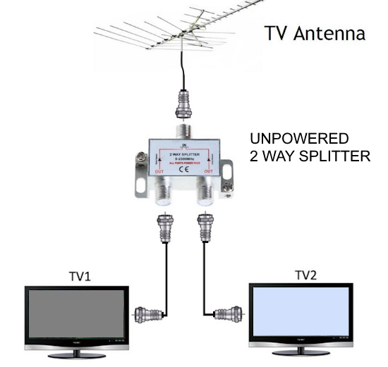
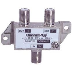
Splitters/Combiners/Diplexers - A splitter is a sort of a Y-adapter. All splitters are bi-directional, and thus will serve also as combiners (watch out for interference). These devices are usually 85%-95% efficient, whether used as splitters or combiners. There are four basic types. They look almost identical, but are very different devices.
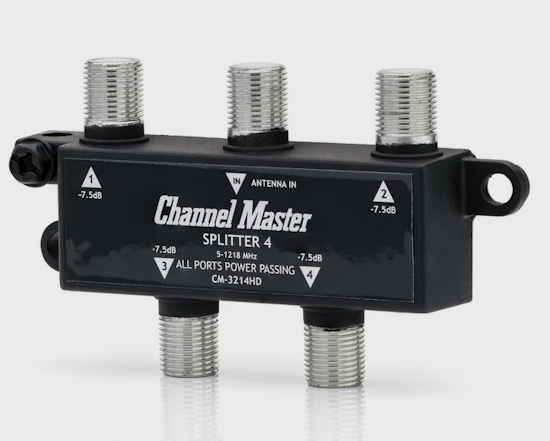
50 MHz - 900 MHz splitter/combiner - Commonly available in 2-way, 3-way, 4-way, and 8-way types, this is the splitter you want if you have multiple TVs or want to gang two identical antennas. The splitter is designed so that it will not cause reflections, but if you leave an output unconnected then there will be reflections. If a 2-way splitter were 100% efficient, you would figure a 3dB loss since each TV would get half the power. Some splitters incorporate a DC Block in one output so that the splitter can be between an amplifier and its power injector.
900 MHz - 2200 MHz splitter/combiner - These can be used with satellite systems, but be sure you know how control issues will be resolved.
VHF/UHF splitter/combiner - This device will split UHF off from the VHF, which would be necessary for TVs with separate VHF and UHF inputs. The device will also combine a VHF antenna with a UHF antenna. The advantage of this splitter is that there is no 3dB loss. (Technically, this device should be called a diplexer.)
Satellite/OTA diplexer - This device will allow a satellite dish and an over-the-air antenna to share the same cable. The loss in the device will not be 3dB, but there will be some small loss. Check for whether DC is blocked to the OTA port. Satellite/OTA diplexers will not work with the new 5-LNB dishes from DirecTV.
Note: Splitters in cable TV systems with "on demand" features must pass 5 MHz - 900 MHz.
Power Passing Splitters:
These unpowered splitters have the capability to pass power through one or more of their ports while also splitting signals to
the TVs.
They can be used between a power inserter unit and the masthead amplifier/aerial.
They allow the 12 volt signal from the power unit to pass through to the masthead amplifier
while also distributing the received amplified signal on the other ports.
Splitters are used as a simple, low cost alternative to amplified TV distribution systems
These splitters work well when the initial signal strength is very good.
Power passing splitters are designed for use with power units and masthead amps
but can work as standard passive splitters as well.
Never use splitters in series (looped one after the other) as this will lead to high levels of signal loss.

When a pre-amp is the only amplifier you need, use a power passing splitter with the power inserter.
Powered Signal Booster/Amplifier
With the small passive splitters, you often will get poor reception if you connect 2 or more TVs. Pixelation can result or no signal at all.
Using a powered splitter will yield much better results. These plug into a wall outlet and can distribute via coaxial cable to multiple TVs.
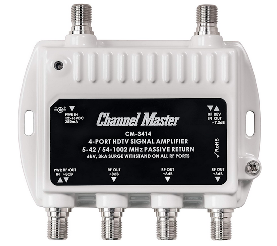
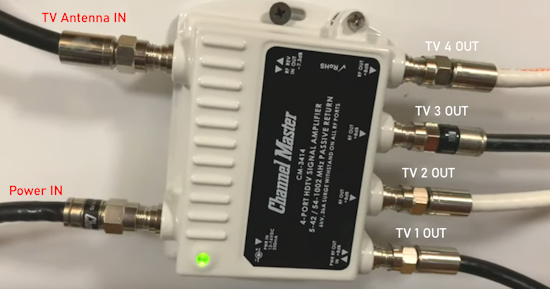
• Channel Master 1 In x 4 Out signal amplifier
Channel Master TV Antenna Amplifier, Signal Booster with 4 Outputs for Connecting Antenna to Multiple TVs
A 3 db gain doubles the signal strength so this distribution amplifier has 8 db gain per port so there should be no problem getting
a great signal to all the TV sets.
Choosing the proper antenna for your setup.
With the information obtained from the links above, you should know where your TV stations are in relation to your home antenna. You should be able to determine if your TV stations are primarily located in the same direction or in many directions and how far away they are from your home antenna. Based on this data, you need to decide if you need an antenna which is good for 20 miles, 30 miles, 40 miles, 60 miles and if it should be UHF, VHF or both. Buy from a known antenna source such as Winegard, Channel Master or their authorized retail dealers. www.winegard.com offers locators for dealers in your area.
Signal Amplifiers, Preamplifiers
If your TV signal is too weak to get a good picture, you could try a good signal booster, amplifier.
There are two types of signal amplifiers: Pre-amp and Distribution amp. Pre-amps are mounted outside on the antenna mast and
are weather and water resistant while distribution amps are mounted inside and are not weather or water resistant. Both types are
going to compensate for weak signals across long coax cable runs. Very weak TV signals can have a lot of noise so keep in mind
that the amplifiers will not only amp up the signal but also the noise as well.
Preamplifiers - the Pre-amp
Generally, TV antennas and pre-amplifiers are
not purchased together as a standard package.
Instead, you would purchase a pre-amplifier separately only if your specific situation requires it to enhance your TV antenna signal.
Here's why and when you might need a TV antenna pre-amplifier:
Weak Signals: If you live in an area with weak TV signals or experience signal degradation due to factors like long cable runs, splitting the signal for multiple TVs, or obstructions like walls or weather conditions, a pre-amplifier can help boost the signal at the antenna before it travels down the cable, improving reception quality.
Long Cable Runs: Long coaxial cable runs can cause significant signal loss. A pre-amplifier placed at the antenna helps compensate for this loss by boosting the signal strength before it traverses the cable, ensuring a stronger signal reaches your TV.
Splitting the Signal: If you're using a signal splitter to connect multiple TVs to a single antenna, signal strength is reduced. A pre-amplifier helps to offset these losses.
Important Considerations:
Not Always Necessary: In areas with strong signals or short cable runs, a pre-amplifier might not be needed and could potentially even over-amplify the signal, leading to pixelation or loss of reception.
Noise Figure: A critical factor in a pre-amplifier is its noise figure. A low noise figure is crucial for digital signals, as it minimizes the additional noise introduced by the amplifier, preserving the signal's integrity.
Matching Components: If your antenna receives VHF and UHF signals, you need a pre-amplifier that passes both frequencies. Ensure that the pre-amplifier's gain is sufficient to compensate for the cable loss in your specific setup.
Installation: Preamplifiers are installed as close to the antenna as possible to amplify the signal before it's degraded by the cable.
While a pre-amplifier is a valuable tool for improving TV antenna reception in certain situations, it is not a standard component included with all TV antennas. It's best to assess your specific needs and consider adding a pre-amplifier only if you're experiencing weak signals or signal loss due to cable runs or splitting.

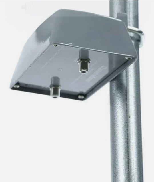
(Mast-mounted amplifiers) - These should be mounted as close to the antenna as possible. Usually the amplifier comes in two parts:
1. The amplifier. This is an outdoor unit that is normally bolted to the antenna mast. It must have a very low noise figure, and enough gain to overcome the cable loss and the receiver's noise figure.
2. The power module (power injector). This is an indoor unit. It is inserted into the antenna cable between the amplifier and the TV. This module injects some power, usually DC, into the coaxial cable where the amplifier can use it. The power injector is the amplifier's power supply.

Power inserters/injectors
Different names for the same thing. They supply power for the pre-amp.
How do power/current and signals coexist on the same cable with power going up the line and signals coming down the line?
It has to do with exactly where the current and where the signal flow on the cable conductor.
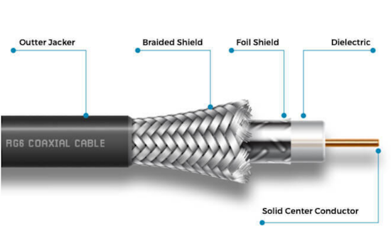
It’s important that you use solid copper center conductors for any cable that carries current.
The signal only exists on the very outer edge of the copper cable. It expands into the white dielectric foam which is designed for this very purpose. That’s why you should never bend a cable hard enough to damage that foam. The relatively large dielectric is part of the reason the cable can carry so much information at the same time.
Where the signal and power/current intersect, on the very outer edge of the cable, there is some interference but it’s more than compensated for by the large areas where there’s only signal or only current.
Coaxial cables were first employed in the mid-19th century and there has been constant improvement to them over time
such as quad-shielding. Coaxial cables are capable of carrying signal and power more efficiently than any other design to date. Systems like power-over-Ethernet are fairly limited in the amount of power they can carry, due to the very thin wires they use. Fiber optics, while incredibly fast, cannot carry power.
Distribution amplifiers -
These are simple signal boosters. They are often necessary when an antenna drives multiple TVs or when the antenna cable is longer than 150 feet. Distribution amplifiers don't need to have a low noise figure, but they need to be able to handle large signals without overloading.
Commonly, distribution amplifiers have multiple outputs. Some handle up to 8 TV sets and many can be connected together so that many more TV sets can be handled. There are also components which allow you to control your media room's gear (satellite receiver, VCR, DVD player) from other rooms in the house where a TV set may be located, by IR remote so that you do not have to leave a room in order to change channels for example.
There should always be a long cable between the preamplifier and any distribution amplifier. Placing the two amplifiers close together can cause overload and/or oscillation.
A mast-mounted amplifier's most important characteristic is its noise level.
Noise level -- Rating
0.5 dB -- superb
2.0 dB -- excellent
4.0 dB -- fair
6.0 dB -- poor
The noise figure is a number you must subtract from the antenna's gain. The noise figure tells how much of the antenna's gain you are throwing away.
Do you need a Pre-Amplifier on your TV Antenna?
If you live far from your local TV transmission towers or you live behind hills partially blocking those TV signals, you may need a Pre-Amplifier.
If on the other hand, you live closer to your local TV towers or are not behind hills so that you are receiving strong signals, then you do
not need a Pre-Amplifier. In fact, using a Pre-Amplifier in this case may actually cause problems because the signal levels could be too high.
Another case where you may need a Pre-Amplifier would be if your Coaxial cable run is more than 50 feet to your TV. Also, if you use
passive splitters, each split will cause signal loss, so using a Pre-Amplifier could help get a stronger signal to the TVs.
Pre-Amplifiers are not all the same so be sure to get one that does the job in your situation. There are Pre-Amplifiers available with
adjustable gain so that you can obtain the optimal signal strength for your reception.
Can I use both a Distribution Power Amplifier and a Pre-amplifier in my TV Antenna Setup?
Yes, you can use a distribution amplifier and a pre-amplifier together in the same antenna system.
However, they must be installed so that they both receive power.
There would probably be no reason for this setup if you are only using one TV. The pre-amp would provide enough signal strength
for one TV. If two or more TVs are connected, then this setup could work.
Antenna connected with a short coax cable to the pre-amplifier Input. Pre-amp Output connected to its power inserter Input or Out to AMP port. Power inserter TO TV port connected to distribution amplifier RF Input port and distribution amplifier Power IN port, to its power adapter.
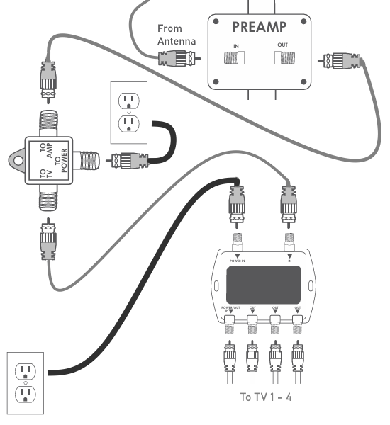
Diagram TV antenna preamp and distribution amp to TVs
TV Signal Reception -
Direction and Distance
The majority of television stations in the USA, 75%, utilize UHF frequencies (RF channels 14-36).
Another 23% broadcast over high-VHF (RF channels 7-13), while a very small number of stations, 2%, broadcast over low-VHF (RF channels 2-6).
For optimal over-the-air (OTA) digital TV reception, the ideal signal level at the TV tuner should be between 60-75 dBµV (or dBmV)
dBmV stands for decibel-millivolts and is a unit of measurement for voltage levels.
You do not want a signal too weak but you do not want a signal too strong either because this can cause issues as well.
Situations where you may benefit from a pre-amp:
• You live far away from the TV broadcast stations
• You are splitting the signal to multiple TVs
• You have very long cable runs between the antenna and the TV (over 50 feet)
pre-amps can be low gain or high gain or adjustable gain.
Situations where a pre-amp may be a disadvantage
• You live close to TV stations and have very strong signals
• You have very short cable runs from antenna to TV
TV Antenna Connection Path:
TV antenna> 1-2 foot of coax cable> Pre-amp> Pre-amp Power inserter> 50 foot coax cable> 4-way splitter> coax cables> TVs
The RG-59 coax cable (thinner) will have greater signal loss than the RG-6 coax cable (thicker). RG-6 is recommended.
Some antennas will already have a built-in pre-amp so adding another pre-amp will usually cause issues. Always check first.
If you are not getting at least a fair signal strength at the antenna, then the pre-amp will not help produce a viewable picture.
The problem is the antenna setup rather than the pre-amp.
TV antennas are not a one size fits all. Each situation is different.
TV Antenna Connection
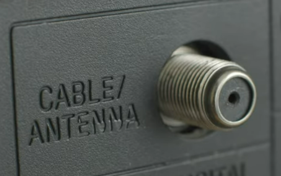
RG-6 Coax Cable is used for TV antenna connections.
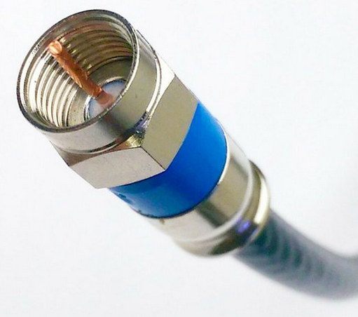
On the TV, the coax cable is connected to the round silver threaded input. Make sure the copper wire is inserted into the pin hole and
then align the threads and turn clockwise until tight.
How do I connect two antennas to one TV?
If your area has TV transmission towers in two different directions, it can be difficult to get strong signals on all channels using only
one TV antenna. You may find yourself constantly repositioning the antenna. One solution may be to install two antennas, one directed to
one location of TV towers and a second antenna directed to the other location of TV towers.
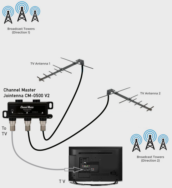
The Channel Master Jointenna has inputs for both antennas and output for the TV.
Note: When combining antennas, it is possible both antennas can receive the same signals. Antenna 1 is receiving a good quality signal on a channel. Antenna 2 receives the same signal but at a fraction of a moment later, and is out of phase with the first signal. This can cause multi-pathing, which ruins the signal quality. Combining antennas may work for your particular situation but it may not end up working as you expected.
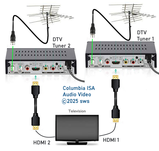
Alternatives for connecting two TV antennas
Use two TV tuners, each with one antenna. This avoids the multi-path issue. You could use the ATSC tuner in the TV and an external TV tuner
such as in a DTV converter box or you could use two DTV converter boxes each with it's output going to two different TV inputs.
One antenna faces in one direction while the second antenna faces in another direction so use the tuner which has the stronger signal for a
given channel. Switch the TV input to the correct tuner.
Connecting cable
The cables used to connect antenna to TV and antenna to pre-amp, splitters and the like is called RF (Radio Frequency) coaxial RG-6 cable. RG stands for Radio Guide. It has a center wire, usually solid copper (18AWG) 75 ohm impedance, and outer insulation all wrapped in a flexible plastic housing. The ends typically use what is called an "F" connector and the connector typically screws on to the jack (In or Out).
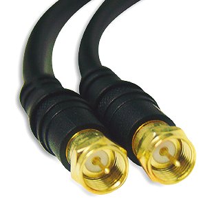
The best RG-6 coax cable is the quad shielded with UV resistant outer jacket. The longer the cable the more signal loss so
only use a length required for the connection. The thicker RG-11 coax cable has solid copper 14AWG center wire and is
somewhat better for longer cable runs of 100 feet or more with regards to signal loss but is more expensive than RG-6 and
less flexible. It does use the same F-type connector. The much thinner RG-59 coax cable (22AWG) is more flexible but suffers
from higher signal loss. RG-6 cable is recommended for most applications. Not all RG-6 cable is the same.
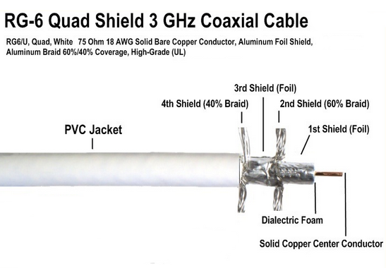
Outdoor Coaxial Cable
Quad shielded RG6 low loss waterproof rubber boot and Ultra-violet light (UV from the sun) resistant coaxial cable for indoor and outdoor use has a flexible and durable weatherproof PVC jacket, and can be used to connect your outdoor TV antenna to indoor devices. CL3 Rated cable is ideal for direct ground burial and in-wall installations. A CL3-rated coax cable indicates it meets Class 3 electrical requirements, meaning it's designed for in-wall use and reduces possible toxic fumes during a fire.
CL3-rated cables are designed to handle up to 300 volts, providing a higher surge capacity than CL2 cables (150 volts).

In addition to the rubber boot protection, you can add electrical tape wrapping over the connections for further
weatherproofing.
Coax Cable Couplers


o Example setup for a home with over-the-air broadcast TV.
Local channels not available with satellite service.
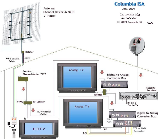
The Channel Master 7777 preamplifier has separate inputs (and separate amplifier circuits) for VHF and UHF, which are then combined without loss. There is a switch inside that will allow VHF and UHF input via the same connector. The unit usually comes with the switch in the separate input position. A second switch disables the FM trap. You have to remove the 4 base screws to access the switches.
If you add a good amplifier to your antenna system and your results get worse instead of better, then you have signal overload and you need to rethink your setup.
An RF splitter can be reversed to form a signal combiner. As long as only one source is "active" at a time, there will be no interference. Turn off the satellite receiver when viewing over-the-air channels and when viewing satellite channels, turn off the DTV converter box. This way you can use the respective remote controls for the boxes and you will not have to get up from your easy chair to switch an A/B switch each time you want to change from satellite to local channels or locals to satellite.
Pre-amps vs Distribution amps
Pre-amps are mounted on the TV antenna mast and amplify the signals right at the antenna with only a very short cable run.
If you are receiving a strong signal from a local TV broadcast tower, the pre-amp can amplify this so all TVs can
potentially get a great signal. The disadvantage is if anything goes wrong with the pre-amp, somebody has to go back up on the roof and replace the amp as opposed to an inside distribution amp which can be replaced much easier.

No outside pre-amp, just a distribution amplifier for multiple TVs.
Home TV Antenna Wiring Diagram
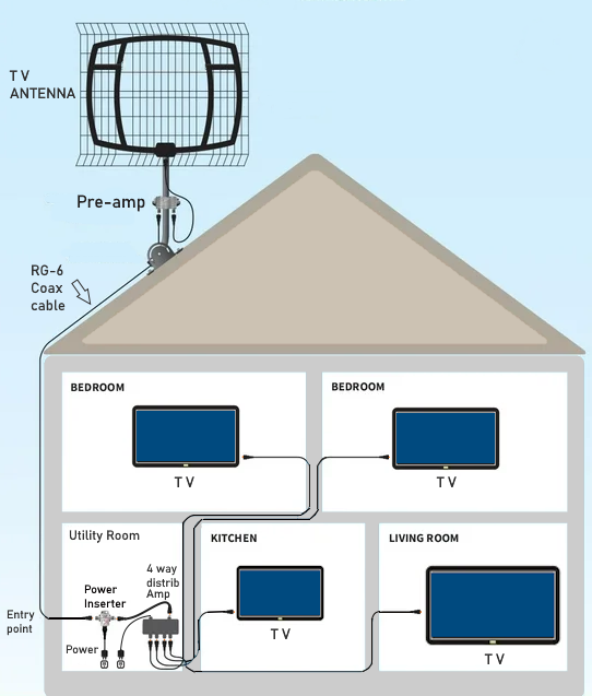
Both a pre-amp and a distribution amplifier for multiple TVs. This setup would be for a weaker TV signal reception or
long cable runs.
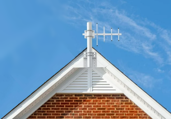
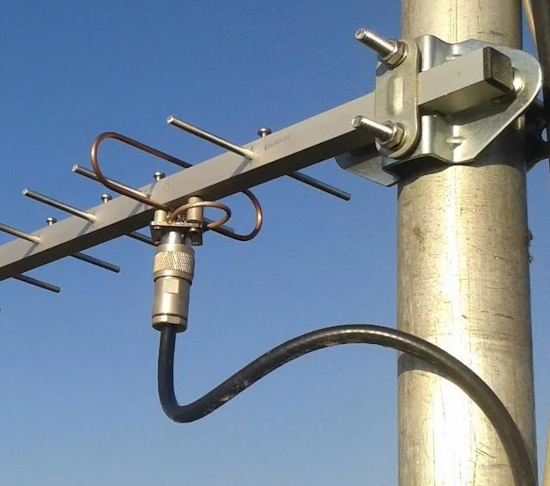
TV Antenna Mounting Locations
TV antennas can be mounted in various locations depending on your mast type and mounting hardware. TV antennas can even be
installed in the attic.
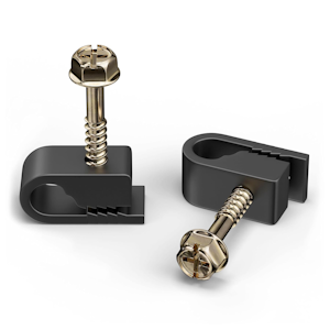
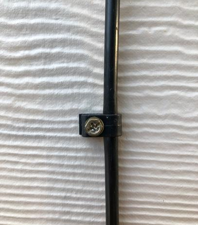
Cable Wiring
Use cable clips or staples specifically designed for coaxial cable to hold the RG-6 firmly against the wall or baseboard, ensuring they don't damage the cable's shielding.
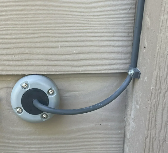
For routing through walls to inside, use waterproof cable clams to seal cabling.
Cable Seals (also known as CableClams) provide waterproof cable routing. These are made of very strong plastic or marine grade 316 stainless steel and come in a variety of colors and finishes. Cable seals fit a wide range of cables and connectors.
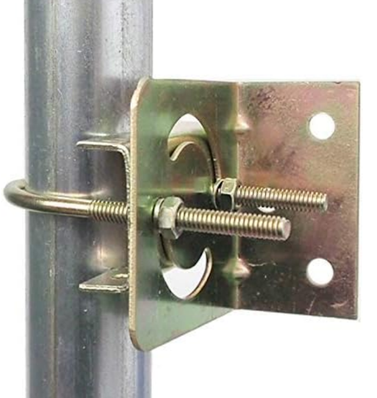
TV Antenna Mast Brackets
Grounding Outdoor TV Antennas
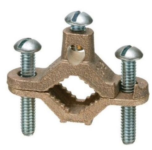
Ground Clamp
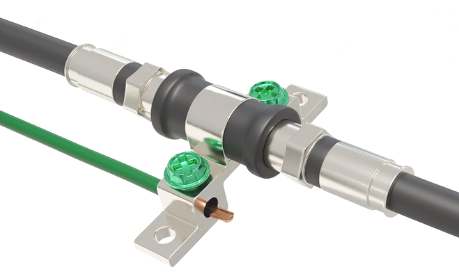
Grounding Block
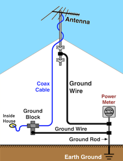
For TVs, the main benefit of grounding is lightning protection. A lightning strike in your neighborhood can generate thousands of volts on the coaxial line. These voltages can damage your equipment.
To reduce these voltages the antenna cable should have a grounding block at the point where it enters the house, and that grounding block should be wired to a ground rod driven into the ground as close as possible to the grounding block.
An effective ground rod is one driven deep enough to reach into moist soil.
The ground rod should also connect to the mast via a heavy wire. #8 aluminum wire is readily available for this. Ground wires should be as short and straight as possible. Turns should be curves with a 6-inch radius. Ground wires do not need insulation.
• TV Antenna Grounding
Scanning for TV Channels
A Smart TV must perform a channel scan before you can view over-the-air channels. Performing a channel scan once a month
or so will pick up any new channels or any channels which have changed their frequency.
To perform a channel scan
select the ANTENNA (TV) input source using the TV remote. In the Main Menu, select SETTINGS or SYSTEM or TUNING and look for
Auto Program, Auto Tuning or Channel Scan or Channel Tuning. Be sure to select AIR and not CABLE.
After the scan is completed, your TV will save the channel list
which will be all the channels your antenna was able to receive. Reposition the antenna and scan again to discover if any new
channels were picked up. Adjust the height and angle of the antenna for optimal reception.
Samsung TV: Home> Source> TV then go to Home> Settings> All Settings> Broadcasting> Auto Tuning> Start> Air
• Channel Scan Samsung TV
Wireless TV Tuner/DVR
Record over-the-air broadcast TV channels in your area.
There are a number of over-the-air TV tuners/DVRs such as the Tablo (4th gen) TV Tuner and DVR which work with your home Wi-Fi to send signals to
your compatible TV or tablet so your antenna can be located away from the TV and the issue of running coaxial cable through walls or ceilings and
connected directly to the TV can be solved.
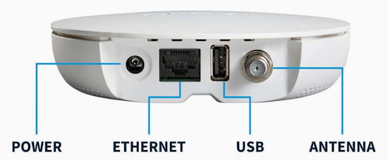
Connect your TV antenna to the Tablo coaxial port. Download the Tablo app which will walk you through the setup process. Connect to your router using
the ethernet port or use your home Wi-Fi. You need the Tablo app on the smart TV (LG WebOS, Samsung, ROKU, Amazon Fire TV).
Some ROKU TV and Amazon sticks are compatible. Download the correct Tablo app.
You can use the two tuner Tablo and stream content to two different TVs,
either live or recorded.
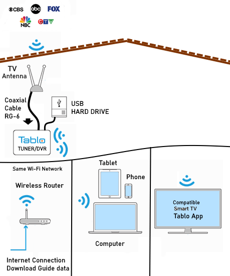
Tablo Connection Diagram
TERMS:
Decibels - Decibels (dB) are commonly used to describe gain or loss in circuits.
UHF - The Ultra High Frequency spectrum is everything from 300 megahertz to 3.0 gigahertz. One of the bands within this spectrum is the TV UHF band, which goes from 470 megahertz (channel 14) to 806 megahertz (channel 69). Each of these stations occupies 6 megahertz of that spectrum.
VHF - The Very High Frequency spectrum is everything from 30 megahertz to 300 megahertz. It is divided into many bands for different purposes (police, fire, aircraft, etc.) Two of the bands within VHF are:
1. The TV VHF-low band. This band goes from 54 megahertz (channel 2) to 88 megahertz (channel 6).
2. The TV VHF-high band. This band goes from 174 megahertz (channel 7) to 216 megahertz (channel 13)
Each channel occupies 6 megahertz of this spectrum. (There is a 4 MHz gap between channels 4 and 5.)
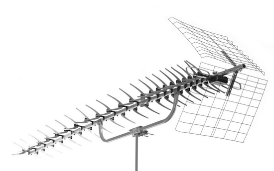
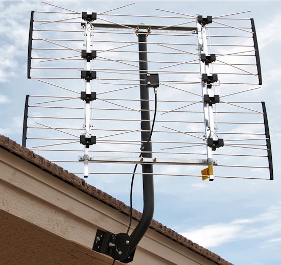
8-Bay antenna - This is a stacked dipole reflector antenna. Its searchlight-like beam makes it very different from the 4-Bay. This highly directional high gain antenna is commonly thought to be the strongest overall UHF antenna. 8-Bays are made by Channel Master, Winegard, and Antennasdirect.com . The Winegard 8-Bay is skewed in favor of the low channels, and is presently the best antenna available for channels 14-30. (If you want an antenna skewed in favor of the high channels, select a big Yagi/Corner-reflector.) 8-Bays are roughly 40x36. 8-bays are intended only for UHF. However the Channel Master 8-bay will pick up channels 7-13 quite well.
BEST OUTDOOR TV ANTENNA
Of all the TV antennas available, if you want the best, the Channel Master CM-3020 is the best choice. Although a bit expensive, you get
the best reception. There are a few different models depending on the range you need.
•
Channel Master Advantage 100 Directional Outdoor TV Antenna - Long Range FM, VHF, UHF and Digital HDTV Antenna CM-3020
Mounting the antenna higher can improve reception from distant TV transmission towers. Installing a signal amplifier could also improve
your reception for weak signals.
See more...
Cable hookup digital cable and TV
HDTV Basic Setup
Columbia ISA Audio Video
Empowering consumers through information.
Contact: columbiaisa@yahoo.com
|
see also:
Audio Video Connections
Video
Connections Diagrams
Cable TV,
Satellite TV, OTA Tuners Receivers
Home Theater
Receivers
|